Startco Engineering Ltd. Page 15
SE-325 Neutral-Grounding-Resistor Monitor Rev. 0
Pub. SE-325-M, May 6, 2008.
7. TEST PROCEDURES
7.1 GROUND-FAULT PERFORMANCE TEST
To meet the requirements of the National Electrical
Code (NEC), as applicable, the overall ground-fault
protection system requires a performance test when first
installed. A written record of the performance test is to
be retained by those in charge of the electrical installation
in order to make it available to the authority having
jurisdiction. A test-record form is provided for recording
the date and the final results of the performance tests.
The following ground-fault system tests are to be
conducted by qualified personnel:
a) Evaluate the interconnected system in accordance with
the overall equipment manufacturer’s detailed
instructions.
b) Verify proper location of the ground-fault current
transformer. Ensure the cables pass through the
ground-fault-current-transformer window. This check
can be done visually with knowledge of the circuit.
The connection of the current-transformer secondary
to the SE-325 is not polarity sensitive.
c) Verify that the system is correctly grounded and that
alternate ground paths do not exist that bypass the
current transformer. High-voltage testers and
resistance bridges can be used to determine the
existence of alternate ground paths.
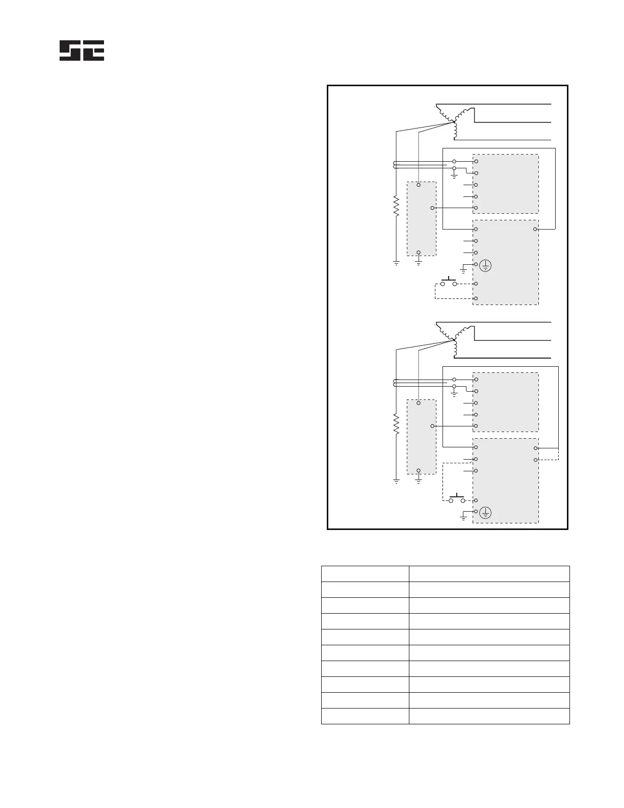
d) Verify proper reaction of the circuit-interrupting
device in response to a simulated or controlled
ground-fault current. To simulate ground-fault
current, use CT-primary current injection. Fig. 12a
shows a test circuit using a Startco SE-400 Ground-
Fault-Relay Test Unit. The SE-400 has a
programmable output of 0.5 to 9.9 A for a duration of
0.1 to 9.9 seconds. Set the test current to 0.6, 2.3, or
4.6 A for SE-325 units set at 0.5, 2.0, or 4.0 A
respectively. Fig. 12b shows a test circuit using a
Startco SE-100T Ground-Fault-Relay Tester. The
SE-100T provides a test current of 0.65 or 2.75 A for
testing 0.5- and 2.0-A trip levels. Inject the test
current through the current-transformer window for at
least 2.5 seconds. Verify that the circuit under test has
reacted properly. Correct any problems and re-test
until the proper reaction is verified.
e) Record the date and the results of the test on the
attached test-record form.
SE-400
SE-325
RMT1
REMOTE
TEST
9
8
1
5
3
11 12
RMT2
L
L
N
N
L1
L1
CT1
CT2
OP1 OP2
L2
L2
a) USING SE-400
0.65 A
2.75 A
NEUTRAL
GROUNDING
RESISTOR
CT200
GROUND-FAULT CT
ER
N
R
G
R
b) USING SE-100T
SE-100T
SE-325
REMOTE
TEST
RMT
L
L
N
N
L1
L1
CT1
CT2
C
L2
L2
NEUTRAL
GROUNDING
RESISTOR
CT200
GROUND-FAULT CT
ER
N
R
G
R
LO
HI
FIGURE 12. Ground-Fault-Test Circuits
TABLE 2. G
ROUND-FAULT-TEST RECORD
D
ATE TEST RESULTS
Retain this record for the authority having jurisdiction.
 Loading...