Startco Engineering Ltd. Page 3
SE-325 Neutral-Grounding-Resistor Monitor Rev. 9
Pub. SE-325-M, May 6, 2008.
3. INSTALLATION
3.1 SE-325
SE-325 outline and mounting details are shown in
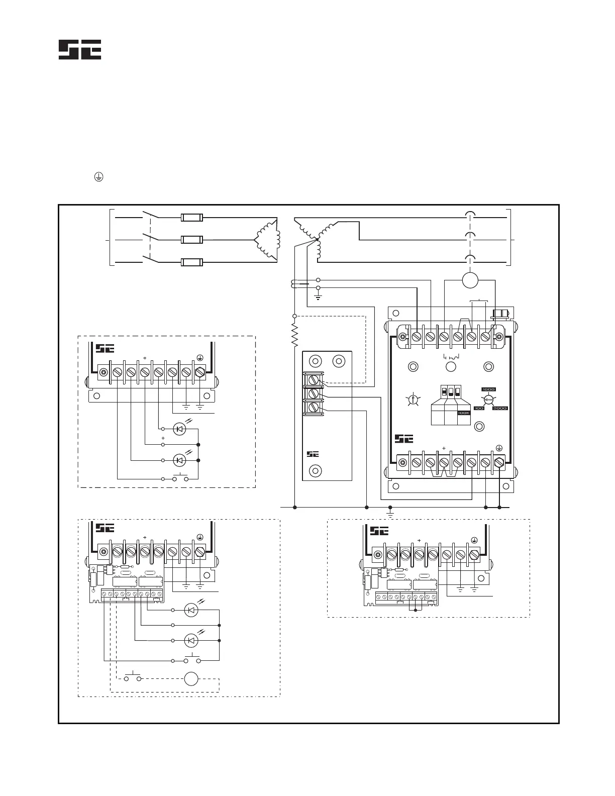
Fig. 2. Typical connections are shown in Fig. 1. Connect
supply voltage to L1 and L2. For a 120-Vac supply,
connect supply neutral to L2. For a direct-current supply,
connect supply negative to L2. Connect chassis-bonding
terminal
to ground.
Connect contact terminals A and B as required.
Face-plate LED's are driven in series with remote-
indication LED's. When remote-indication LED’s are not
used, terminals GI, +, and RI must be connected for the
face-plate LED’s to operate. These jumpers are installed
at the factory.
Install the upper terminal-block cover to prevent
inadvertent contact with line terminals.
N
R
G
ER-600VC
SENSING RESISTOR
20 K
600 VAC MAX
W
STARTCO
ENGINEERING LTD.
MADE IN SASKATOON, CANADA
600 V
4160 V
SUPPLY
NEUTRAL
GROUNDING
RESISTOR
CT200
GROUND-FAULT CT
UV
120 VAC
L
N
LOAD
RESISTOR-FAULT
INDICATOR
GROUND-FAULT
INDICATOR
RESET SWITCH
REMOTE INDICATION AND RESET
RED
RED
F1
RESET
POWER
GROUND
FAULT
GF TRIP
TIME (s)
RESIST
OR
FAULT
RES TRIP
LEVEL (VAC)
CT1
CT2
AB
RIGISW
L1
R
L2
G
STARTCO
ENGINEERING LTD.
NGR MONITOR
SE-325
MODE
RESGF
20 400
200
0.1 2.0
1.0
4.0 A
2.0 A
0.5 A
SH
UV 20K
RIGISW R G
STARTCO
ENGINEERING LTD.
NGR MONITOR
SE-325
ER
R
S
1
R
S
2
C
G
I
G
R
I
+
S
W
K1 K2
SW CI/GI +
GI/RI
TB1
RESISTOR-FAULT
INDICATOR
GROUND-FAULT
INDICATOR
RESET SWITCH
RED
RED
RK-13 CONNECTION WITH REMOTE INDICATION AND RESET
ALTERNATE
RESET CIRCUIT
24-120 Vac/Vdc
RK-13 CONNECTION WITHOUT REMOTE INDICATION OR RESET
K1 K2
RI
+
GI
SW
RIGISW R G
STARTCO
ENGINEERING LTD.
NGR MONITOR
SE-325
RI
GI
SW
ER
R
S
1
R
S
2
C
G
I
G
R
I
+
S
W
K1 K2
SW CI/GI +
GI/RI
TB1
K1 K2
RIGISW R G
STARTCO
ENGINEERING LTD.
NGR MONITOR
SE-325
ER
NOTES:
1. ALTERNATE SENSING-RESISTOR TERMINAL-N CONNECTION,
THE NEUTRAL CONNECTION IS NOT MONITORED.
2
. K1 CLOSES ON GROUND-FAULT TRIP.
3. K2 CLOSES ON RESISTOR-FAULT TRIP.
4. VOLTAGE BETWEEN ER TERMINALS R AND G
LIMITED TO 100 V BY INTERNAL CLAMP.
CAUTION: DO NOT USE K1 OR K2 IN A TRIP CIRCUIT.
NOTE 1
NOTES 2 & 3
NOTE 4
FIGURE 1. Typical Application.
 Loading...