10
5 CommIssIonInG
ѥ
INSTALLER TIP: Make up a short cable and perform steps 5.1 to 5.5 with the LCD touchpad
in the ceiling space next to the main modules.
5.1 Before Connecting System Power Supply
1. Ensure that all modules are correctly mounted and the power supply is connected
properly.
2. Ensure that all touchpads and motors are connected as per the connection diagram
supplied.
ѥ
DO NOT CONNECT Z-PLUS TOUCHSCREEN TO MOTOR OUTPUTS.
3. (QVXUHWKHXQLWLQWHUFRQQHFWFDEOHLV¿WWHGDVSHUWKHFRQQHFWLRQGLDJUDP
',36ZLWFK&RQ¿JXUDWLRQ
1. Additional features can be enabled by setting the 8 way DIP switch at the Z-Plus MPM.
DIP selection table appears in section 3.2.3.
5.3 Initial Power Check
:KHQSRZHULVDSSOLHGWRWKHV\VWHPWKHVWDUWXSURXWLQHZLOOGULYHDOO]RQHGDPSHUPRWRUVWR
the fully open position, then all dampers will drive to the appropriate position as dictated by
the zone status and set parameters.
1. Connect the 24 VAC power supply to the MyZone system.
2. Check the main modules for fault LEDs (any red LED indicates an excess current fault
on the output - generally a cable short).
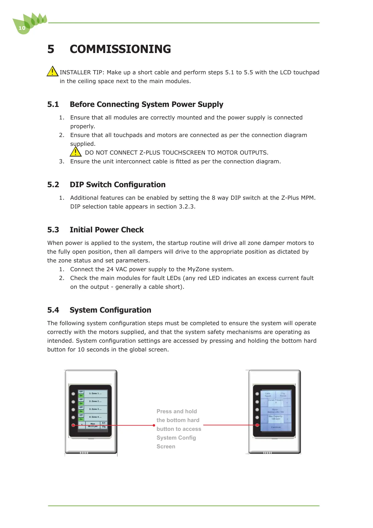
6\VWHP&RQ¿JXUDWLRQ
7KHIROORZLQJV\VWHPFRQ¿JXUDWLRQVWHSVPXVWEHFRPSOHWHGWRHQVXUHWKHV\VWHPZLOORSHUDWH
correctly with the motors supplied, and that the system safety mechanisms are operating as
LQWHQGHG6\VWHPFRQ¿JXUDWLRQVHWWLQJVDUHDFFHVVHGE\SUHVVLQJDQGKROGLQJWKHERWWRPKDUG
button for 10 seconds in the global screen.
Press and hold
the bottom hard
button to access
6\VWHP&RQ¿J
Screen
Cfg
A/C
Mon
08.23 pm
5
On
Off
4: Zone 4 ...
On
Off
3: Zone 3 ...
On
Off
2: Zone 2 ...
On
Off
1: Zone 1 ...
Cfg
A/C
Mon
08.23 pm
5
On
Off
4: Zone 4 ...
On
Off
3: Zone 3 ...
On
Off
2: Zone 2 ...
On
Off
1: Zone 1 ...