EasyManua.ls Logo

Lochinvar 100 Series - User Manual

Lochinvar 100 Series
64 pages
Print Icon
To Next Page IconTo Next Page
Loading...
PLACE THESE INSTRUCTIONS ADJACENT TO HEATER AND NOTIFY OWNER TO KEEP FOR FUTURE REFERENCE.
KEEP THIS MANUAL IN THE POCKET ON HEATER FOR FUTURE REFERENCE WHENEVER MAINTENANCE
ADJUSTMENT OR SERVICE IS REQUIRED.
PRINTED 0522 100358519_2000199939G
Instruction Manual
COMMERCIAL ELECTRIC WATER HEATERS
300 Maddox Simpson Parkway
Lebanon, TN 37090
Technical Service Phone: 1-800-722-2101
Technical Service email: 2tech@lochinvar.com
www.Lochinvar.com
LOW LEAD
CONTENT
LISTED
Thank you for buying this energy efcient water heater. We
appreciate your condence in our products.
Read and understand this instruction
manual and the safety messages
herein before installing, operating or
servicing this water heater.
Failure to follow these instructions and
safety messages could result in death
or serious injury.
This manual must remain with the
water heater.
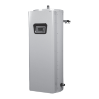
MODELS LHS 50/80/119 Series 100
& LHC 50/80/119 Series 100
Installation - Service
- Maintenance - Operation
If the water heater becomes immersed in water up to or
above the level of the bottom of the element doors,
the heater should be examined by a qualified service
agency before it is placed in operation.
Electrical Shock Hazard

Table of Contents

Other manuals for Lochinvar 100 Series

Questions and Answers

  • M
    Mary BergerJul 29, 2025
    What to do if my Lochinvar Water Heater heat pump is not running due to electrical issues?
    • A
      Amber BurnsJul 29, 2025
      If your Lochinvar Water Heater's heat pump isn't running due to electrical issues, first, refer to the nameplate for unit requirements. Then, check the field wiring diagram and tighten all connections. Also, inspect for loose wiring and tighten those connections as well. Other solutions include replacing the thermostat or resetting the phase monitor. If those steps don't resolve the issue, consider replacing the compressor.
  • B
    Brian MosleyAug 2, 2025
    What to do if my Lochinvar 100 heat pump is not running due to a high-pressure fault?
    • H
      Holly Wilson DDSAug 2, 2025
      If your Lochinvar Water Heater's heat pump isn't running due to a high-pressure fault, ensure the thermostat setting does not exceed 160°F. Let the heat pump remain off until the room temperature returns to its operating range. Other potential solutions include replacing the unit pump, reducing piping or adding a booster pump, cleaning the heat exchanger with a mild acid wash, and ensuring all shut-off valves are open.
  • M
    Michael FreemanAug 7, 2025
    What to do if my Lochinvar Water Heater heat pump is not running due to a low-pressure fault?
    • J
      Jose PowellAug 7, 2025
      If the heat pump of your Lochinvar Water Heater isn't running due to a low-pressure fault, allow the heat pump to remain off until the room temperature returns to its operating range. Address any air-flow issues by replacing or realigning the pulley assembly and tightening the belt at the adjustable pulley, replacing filters, or relocating the unit to allow for even airflow. Also, find the source of any leaks, repair them, and recharge the system.
  • S
    Stacy MercadoAug 13, 2025
    Why is the water from my Lochinvar Water Heater never hot enough?
    • A
      amandacooperAug 13, 2025
      If the water from your Lochinvar Water Heater is never hot enough, you can try the following: set the thermostat for the storage tank to a higher temperature. Alternatively, increase the size of the storage tank or install a gas or electric heater to compensate for the shortfall. If the room air temperature is too cool, use backup water heating, duct cool air to another space, or duct warmer air from another space to the installed room.
  • M
    mark87Aug 18, 2025
    What to do if there is water on the floor around my Lochinvar Water Heater heat pump and/or water tank?
    • R
      Robert NorrisAug 18, 2025
      If you find water on the floor around your Lochinvar Water Heater's heat pump and/or water tank, start by repairing any leaks as necessary. Shim the unit to ensure it's level. Ensure the condensate trap depth maintains a water column during operation. You can also use a pipe snake or compressed air to remove any obstructions. Finally, consider covering the bottom of the unit with foam insulation.
  • A
    Aaron SmallAug 22, 2025
    How to fix a noisy Lochinvar 100 heat pump?
    • W
      William RandallAug 22, 2025
      To address a noisy Lochinvar Water Heater heat pump, try the following: tighten fasteners, place vibration dampers underneath the unit, or tighten or align pulleys.

Summary

SAFE INSTALLATION, USE, AND SERVICE

IMPORTANT DEFINITIONS

Defines terms like "Qualified Installer or Service Agency" for proper understanding.

APPROVALS

Lists certifications and standards the product complies with.

GENERAL SAFETY INFORMATION

DO NOT OPERATE IF DAMAGED

Instructions on handling units exposed to fire, damage, or operating without water.

GROUNDING INSTRUCTIONS

Mandates grounding according to electrical codes to prevent shock and ensure system operation.

LIMITING THE RISK OF SCALDING

Advises on preventing dangerously hot water from reaching fixtures using mixing valves.

HYDROGEN GAS (FLAMMABLE)

Warns about potential hydrogen gas buildup and ignition risks in unused water heaters.

HAZARD MESSAGES

GENERAL SAFETY WARNINGS

Consolidates various warnings including electrical shock, burn, explosion, and toxic chemical hazards.

PROPERTY DAMAGE HAZARDS

Highlights risks of leaks and improper discharge pipe installation causing property damage.

INTRODUCTION

PREPARING FOR THE INSTALLATION

Outlines crucial pre-installation steps like reading the manual and understanding codes.

GENERAL INSTALLATION REQUIREMENTS

Specifies compliance with national/local codes, power company rules, and NSF standards.

FEATURES AND COMPONENTS

LHS;LHC MODEL DIFFERENCES

Explains the distinction between LHS (Surface Mount Control) and LHC (Electronic Control) models.

ELECTRONIC CONTROL MODEL COMPONENTS

Identifies key components of the electronic control model, shown in Figure 1.

FEATURES AND COMPONENTS

SURFACE MOUNT CONTROL MODEL COMPONENTS

Identifies key components of the surface mount control model, shown in Figure 2.

FEATURES AND COMPONENTS

MODEL AND RATING PLATE

Details the information found on the unit's model and rating plate for identification.

INSTALLATION CONSIDERATIONS

LOCATING THE WATER HEATER

Provides guidance on selecting an appropriate location for the water heater, considering safety and economy.

INSTALLING THE WATER HEATER

REQUIRED ABILITY

Specifies the necessary skills for installation, equivalent to a qualified agency.

THERMOSTATIC POINT-OF-USE MIXING VALVES

Explains the importance and function of mixing valves to prevent scalds.

CONTAMINATED WATER

Warns against connecting to non-potable water systems or using boiler treatment chemicals.

INSTALLING THE WATER HEATER

TEMPERATURE-PRESSURE RELIEF VALVE

Details requirements and installation of the T&P relief valve for safety against explosion.

INSULATION BLANKETS

Discusses the optional use of insulation blankets and installation precautions.

INSTALLING THE WATER HEATER

WATER LINE CONNECTIONS

Refers to piping diagrams for installation methods and recommends dielectric unions.

CLOSED WATER SYSTEMS

Explains how closed systems can affect water pressure and tank integrity.

THERMAL EXPANSION

Describes thermal expansion issues in closed systems and the need for expansion tanks.

ELECTRICAL INSTALLATION

Covers grounding, circuit requirements, and voltage tolerances for safe electrical hookup.

START UP AND OPERATION

FILLING THE WATER HEATER

Provides essential steps and warnings for filling the water heater before operation.

INITIAL START UP CHECKS

Lists checks for water and electrical connections, and initial operation observation.

TEMPERATURE REGULATION

LIMITING THE RISK OF SCALDING

Reemphasizes preventing scalds by adjusting temperature and using mixing valves.

HIGH TEMPERATURE LIMIT CONTROLS (ECO)

Explains the function and reset procedure for ECO high-temperature limit controls.

TEMPERATURE REGULATION

THERMOSTAT SETTINGS - SURFACE MOUNT CONTROL

Details how to set thermostats on surface mount models, including specific types.

THERMOSTAT SETTINGS - ELECTRONIC CONTROLS

Explains how to adjust the operating set point via the UIM for electronic control models.

CONTROL SYSTEM OPERATION

THE HOME SCREEN

Describes the default display, model information, tank temperature, and status.

CONTROL SYSTEM NAVIGATION

Explains how to use the UIM buttons (Up/Down, Operational) for menu navigation.

CONTROL SYSTEM OPERATION

STATUS ICONS

Provides a table explaining various status icons displayed on the LCD screen.

OPERATING STATES

Defines different operating states like Standby, Heating, Alert, and Fault.

CONTROL SYSTEM OPERATION

MENUS OVERVIEW

Lists and describes the various menus accessible through the control system.

CONTROL SYSTEM OPERATION

TEMPERATURES MENU

Details how to adjust Operating Set Point, differentials, and probe offset for temperature control.

CONTROL SYSTEM OPERATION

ADJUSTING OPERATING SET POINT AND DIFFERENTIALS

Step-by-step guide on modifying temperature settings via the control system interface.

CONTROL SYSTEM OPERATION

ECONOMY MODE SETUP MENU

Explains how to set up economy mode for reduced operating costs during specific periods.

CONTROL SYSTEM OPERATION

TIME CLOCK SETTINGS

Instructions for setting the current time and day for the control system.

CONTROL SYSTEM OPERATION

DAILY OPERATING MODE SETTINGS

How to configure daily operating modes (Normal, Economy) for each day of the week.

CONTROL SYSTEM OPERATION

ALARM OUTPUT SETUP MENU

Configuration options for the alarm relay to notify of specific operational conditions.

CONTROL SYSTEM OPERATION

DISPLAY SETTINGS MENU

Options for customizing display units, backlight, and contrast on the UIM.

HEATER INFORMATION MENU

Access to non-adjustable operational data like elapsed time and cycle counts.

CONTROL SYSTEM OPERATION

CURRENT FAULT; ALERT MENU

Displays active faults or alerts, with a "(none)" indicator if none are present.

FAULT HISTORY MENU

Records the last 9 faults/alerts with timestamps for troubleshooting intermittent issues.

CONTROL SYSTEM OPERATION

FAULT OCCURRENCE MENU

Provides a running total of each individual fault condition that has occurred.

RESTORE FACTORY DEFAULTS MENU

Allows resetting most user settings back to their original factory defaults.

MAINTENANCE

ANODE ROD MAINTENANCE

Instructions for inspecting and replacing powered and sacrificial anode rods for tank protection.

MAINTENANCE

TEMPERATURE-PRESSURE RELIEF VALVE TEST

Procedure for manually testing the T&P relief valve to ensure proper operation.

DRAINING AND FLUSHING

Steps for draining and flushing the tank to reduce sediment buildup.

MAINTENANCE

LIME SCALE REMOVAL

Methods for removing lime scale from heating elements using specific cleaning agents.

TROUBLESHOOTING

NOT ENOUGH OR NO HOT WATER

Troubleshooting steps for issues related to insufficient or no hot water supply.

WATER IS TOO HOT

Directs users to the temperature regulation section for addressing overheating issues.

WATER HEATER MAKES STRANGE SOUNDS

Explains common noises and their causes, such as sediment or normal component operation.

TROUBLESHOOTING

CHECKING FOR LEAKS

A guide to identifying and correcting potential water leak points on the heater.

DIAGRAMS

CONTROL CIRCUIT TRANSFORMER CONNECTIONS

Illustrates transformer connections for the control circuit in electronic models.

DIAGRAMS

CENTRAL CONTROL BOARD (CCB) CONTROL CIRCUIT DIAGRAM

Detailed wiring diagram for the CCB's control circuit in electronic models.

DIAGRAMS

POWER CIRCUIT DIAGRAMS - SURFACE MOUNT CONTROL MODELS

Wiring diagrams for the power circuits of surface mount control models (3 and 6 elements).

DIAGRAMS

NINE ELEMENTS - SINGLE AND THREE PHASE

Wiring diagram for nine-element models, showing single and three-phase conversions.

DIAGRAMS

POWER CIRCUIT DIAGRAMS - ELECTRONIC CONTROL MODELS

Wiring diagrams for the power circuits of electronic control models (3 and 6 elements).

DIAGRAMS

NINE ELEMENT - SINGLE AND THREE PHASE

Wiring diagram for nine-element electronic control models, showing phase conversions.

PIPING DIAGRAMS

COMMERCIAL ELECTRIC - (1 UNIT)

Suggested piping configuration for a single commercial electric water heater unit.

PIPING DIAGRAMS

COMMERCIAL ELECTRIC - (1 UNIT) WITH VERTICAL STORAGE TANK

Piping diagram for a single unit with a vertical storage tank.

PIPING DIAGRAMS

COMMERCIAL ELECTRIC - (1 UNIT) WITH HORIZONTAL STORAGE TANK

Piping diagram for a single unit with a horizontal storage tank.

PIPING DIAGRAMS

COMMERCIAL ELECTRIC - (2 UNITS)

Suggested piping configuration for two commercial electric water heater units.

PIPING DIAGRAMS

COMMERCIAL ELECTRIC - (2 UNITS) WITH VERTICAL STORAGE TANK

Piping diagram for two units with vertical storage tanks.

PIPING DIAGRAMS

COMMERCIAL ELECTRIC - (2 UNITS) WITH HORIZONTAL STORAGE TANK

Piping diagram for two units with horizontal storage tanks.

PIPING DIAGRAMS

COMMERCIAL ELECTRIC - (3 UNITS)

Suggested piping configuration for three commercial electric water heater units.

PIPING DIAGRAMS

COMMERCIAL ELECTRIC - (3 UNITS) WITH VERTICAL STORAGE TANK

Piping diagram for three units with vertical storage tanks.

PIPING DIAGRAMS

COMMERCIAL ELECTRIC - (3 UNITS) WITH HORIZONTAL STORAGE TANK

Piping diagram for three units with horizontal storage tanks.

PIPING DIAGRAMS

COMMERCIAL ELECTRIC - (4 UNITS)

Suggested piping configuration for four commercial electric water heater units.

PIPING DIAGRAMS

COMMERCIAL ELECTRIC - (4 UNITS) WITH VERTICAL STORAGE TANK

Piping diagram for four units with vertical storage tanks.

PIPING DIAGRAMS

COMMERCIAL ELECTRIC - (4 UNITS) WITH HORIZONTAL STORAGE TANK

Piping diagram for four units with horizontal storage tanks.

Lochinvar 100 Series Specifications

General IconGeneral
BrandLochinvar
Model100 Series
CategoryWater Heater
LanguageEnglish

Related product manuals