14 • Commercial Electric Water Heaters
Installing the Water Heater
The temperature-pressure relief valve must be manually operated
at least once a year. Caution should be taken to ensure that (1) no
one is in front of or around the outlet of the temperature-pressure
relief valve discharge line, and (2) the water manually discharged
will not cause any bodily injury or property damage because the
water may be extremely hot. If after manually operating the valve, it
fails to completely reset and continues to release water, immediately
close the cold water inlet to the water heater, follow the draining
instructions in this manual, and replace the temperature-pressure
relief valve with a properly rated/sized new one.
If you do not understand these instructions or have any questions
regarding the temperature-pressure relief valve call the toll free
number listed on the back cover of this manual for technical
assistance.
WATER LINE CONNECTIONS
This manual provides detailed piping installation diagrams. See
Piping Diagrams (page 49) for typical methods of application.
For the heater inlet and outlet connections, dielectric unions are
recommended. The water heater may be installed by itself, or with a
separate storage tank, on both single and two-temperature systems.
When used with a separate storage tank, the circulation may be either
by gravity or by means of a circulating pump. When a circulating
pump is used it is important to note that the ow rate should be
slow so that there will be a minimum of turbulence inside the heater.
CLOSED WATER SYSTEMS
Water supply systems may, because of code requirements or such
conditions as high line pressure, among others, have installed
devices such as pressure reducing valves, check valves, and back
ow preventers. Devices such as these cause the water system to
be a closed system.
THERMAL EXPANSION
As water is heated, it expands (thermal expansion). In a closed
system the volume of water will grow when it is heated. As the
volume of water grows there will be a corresponding increase in
water pressure due to thermal expansion. Thermal expansion can
cause premature tank failure (leakage). This type of failure is not
covered under the limited warranty. Thermal expansion can also
cause intermittent temperature-pressure relief valve operation:
water discharged from the valve due to excessive pressure build
up. This condition is not covered under the limited warranty. The
temperature-pressure relief valve is not intended for the constant
relief of thermal expansion.
A properly sized thermal expansion tank must be installed on all
closed systems to control the harmful eects of thermal expansion.
Contact a local plumbing service agency to have a thermal expansion
tank installed.
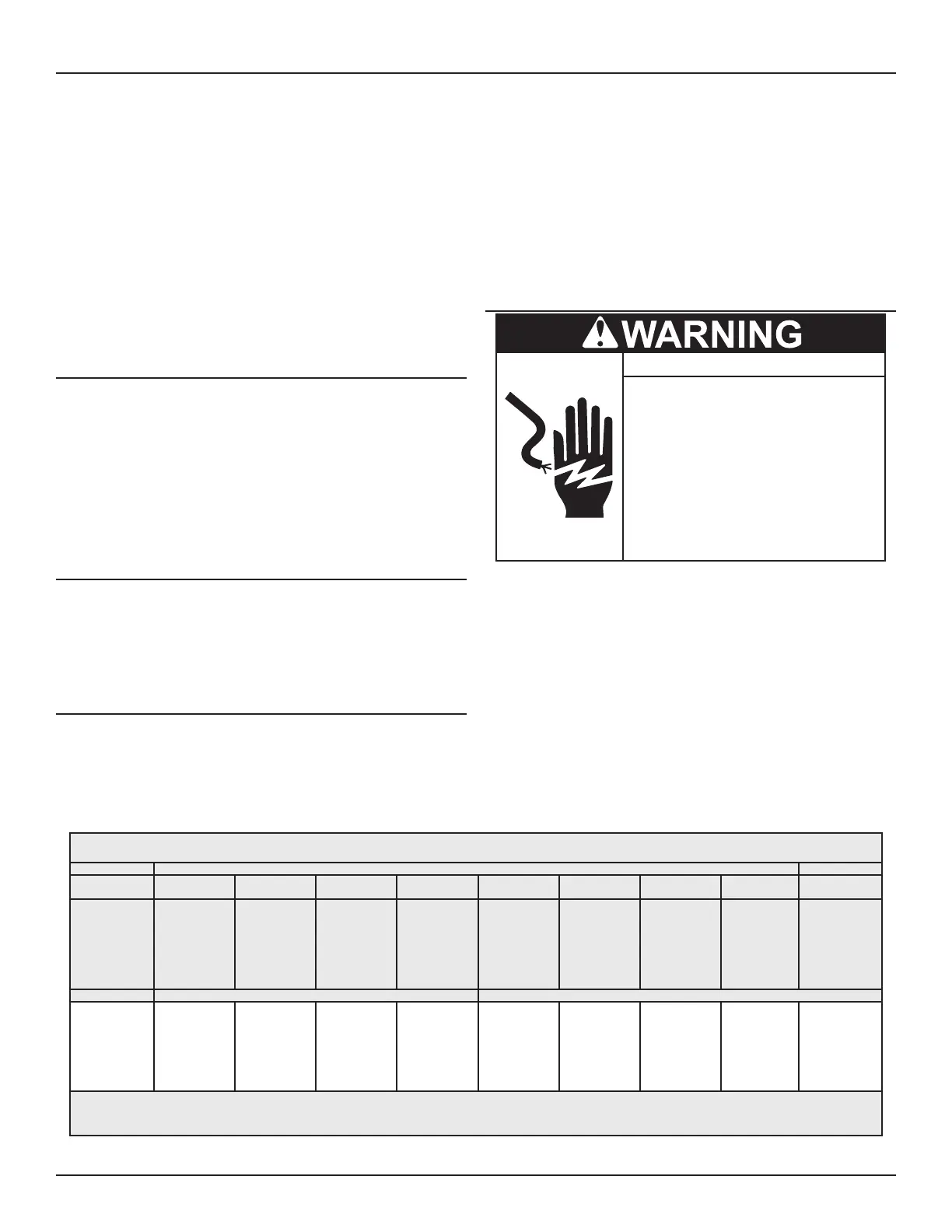
ELECTRICAL
Turn off power at the branch circuit
breaker serving the water heater
before performing any service.
Electrical Shock Hazard
•
Label all wires prior to disconnecting
when performing service. Wiring errors
can cause improper and dangerous
operation.
•
Verify proper operation after servicing.
•
Failure to follow these instructions can
result in personal injury or death.
•
The installation must conform with these instructions and the local
code authority having jurisdiction and the requirements of the power
company. In the absence of local codes, the installation must comply
with the current editions of the National Electrical Code, NFPA 70 or the
Canadian Electrical Code CSA C22.1.
An electrical ground is required to reduce risk of electrical shock
or possible electrocution. The water heater should be connected
to a separate grounded branch circuit with over-current protection
and disconnect switch. The water heater should be grounded in
accordance with national and local codes.
Voltage applied to the heater should not vary more than +5% to -10%
of the model and rating plate marking for satisfactory operation.
Table 3. Allowable Ampacities of Insulated Conductors
Not More Than Three Conductors in Raceway or Cable or Earth (Directly Buried), Based on Ambient Temperature of 30°C (86°F)
Size Temperature Rating of Conductor Size
60°C
(140°F)
75°C
(167°F)
85°C
(185°F)
90°C
(194°F)
60°C
(140°F)
75°C
(167°F)
85°C
(185°F)
90°C
(194°F)
AWG
MCM
TYPES
RUW, T
TW, UF
TYPES
FEPW
RH, RHW
RUH,
THW,
THWN,
XHHW
USE, ZW
TYPES
V, MI
TYPES
TA, TBS
SA, AVB
SIS, =FEP,
=FEPB,
=RHH,
=THHN,
=XHHW*
TYPES
RUW, T
TW, UF
TYPES
RH, RHW
RUH
THW,
THWN
XHHW,
USE
TYPES
V, MI
TYPES
TA, TBS,
SA, AVB
SIS,
=RHH,
=THHN,
=XHHW*
AWG
MCM
COPPER ALUMINUM OR COPPER-CLAD ALUMINUM
18
16
14
12
10
8
......
......
15
20
30
40
......
......
15
20
30
45
......
22
25
30
40
50
21
22
25
30
40
50
......
......
......
15
25
30
......
......
......
15
25
40
......
......
......
25
30
40
......
......
......
25
30
40
......
......
......
12
10
8
+ The load current rating and the overcurrent protection for these conductors shall not exceed 15 amperes for 14 AWG. 20 amperes for 12 AWG.
and 30 amperes for 10 AWG copper; or 15 amperes for 12 AWG and 25 amperes for 10 AWG aluminum and copper-clad aluminum.
* For dry locations only. See 75°C column for wet locations.
 Loading...