10
7. Troubleshooting
Type of Malfunction Possible Cause Correction
Rotor does not run or – Controller incorrectly adjusted. • Check the settings in the PERIPHERY
does not reach full speed. SET-UP directory (see operating
The error message (with instructions for the Controller 97123).
beeping) blinks in the – Loose plug or connector on the • Switch the power switch (controller) to
digital display: connection cord. position O (OFF). Tighten the plug or
the connector of the connection cord.
Switch the power switch to the
position I (ON).
– Connection cord defect. • Replace the connection cord.
– Rotor was restricted in its mechanical • Check the installation.
movement and switched off.
Message in the upper line – Rotorspray motor assembly or bearing • Replace the rotorspray motor assembly
= Channel A assembly defect. or the bearing assembly (see below).
Message in lower line – Controller defect. • Loctite Service.
= Channel B
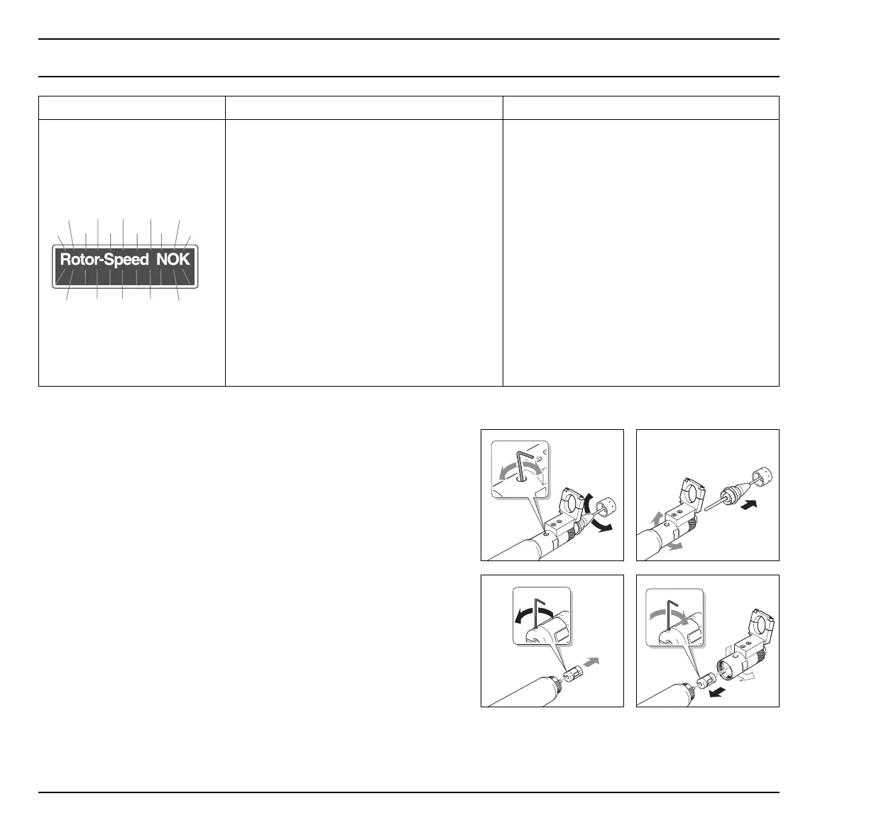
Replacement of motor assembly or bearing assembly
• Turn drive assembly 5 until the fastening screw
of the shaft coupling can be seen in the
access hole 3.
Loosen the shaft coupling.
• Remove drive assembly 5 and rotor disc 6
together with shaft.
• Remove rotorspray front end assembly 2 from
rotorspray motor assembly 1 and replace the
defective part (without coupling).
• Screw rotorspray front end assembly 2 into the
rotorspray motor assembly 1.
• Insert the shaft with the drive assembly 2 into
the rotorspray motor assembly 1.
• Insert the shaft with the drive assembly 5 and
the rotor disc 6 to the stop.
• Tighten the shaft coupling again.