Logosol Multifunctional Servo Drive LS-231SE
Doc # 712231004 / Rev. A, 05/05/2011
Logosol, Inc. • 1155 Tasman Drive • Sunnyvale, CA 94089 Tel: (408) 744-0974 • www.logosolinc.com
27
Amplifier interface and Step & Direction interface.
If Analog mode is selected, ADC (analog input) is differential and may be adjusted between ±2.5V to
±10.0V. The load is 10K.
“Analog offset” is a constant added to the amplifier’s input control voltage and can be used in
applications with asymmetric load. Refer to Safety Features - LS-231SE diagnostic and I/O section for
Analog mode description.
Step & Direction mode uses the same interface. In this mode Step, Dir (direction) and AEN (enable)
inputs are active. Refer to Safety Features - LS-231SE diagnostic and I/O section for Step & Direction
mode description.
Fault output and Encoder (+A, -A, +B, -B, +Z, -Z) outputs are TTL compatible.
All digital inputs are HC (high speed CMOS) compatible and with 4K7 pull-down resistors.
Serial Command Interface
Serial communication with the LS-231SE adheres to a full-duplex (4 wire) 8-bit asynchronous protocol
with one start bit, followed by 8 data bits (lsb first), followed by a single stop bit.
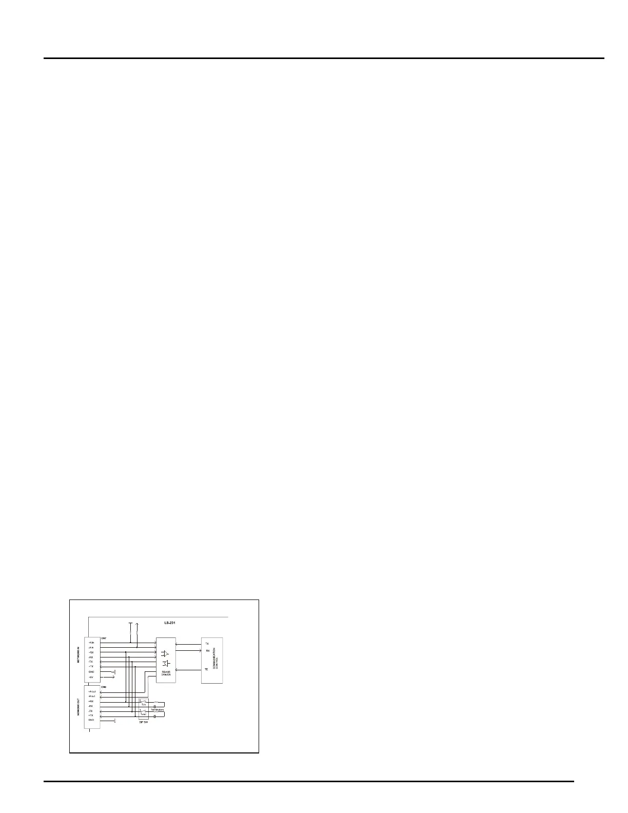
The communication protocol supports full-duplex multi drop RS-485 interface that allows multiple drives
to be controlled over a single RS-485 port. The host sends commands over it’s RS-485 transmit line and
receives all status data over shared RS-485 receive line.
The command protocol is a strict master/slave protocol in which the host sends a command packet to a
specific slave. The data are stored in the slave buffer until the end of the servo cycle (51.2µS) and then
the command is executed. Then the slave Drive sends back a status packet. Typically the host does not
send another command until a status packet has been received to insure that it does not overwrite any
previous command data still in use.
Each command packet consist of:
Header byte (0xAA)
Address byte – individual or group (0x00 – 0xFF)
Command byte
0 – 15 data bytes
Checksum byte
The command byte is divided into upper and lower nibbles: the lower nibble is the command value; the
upper nibble is the number of additional data bytes, which will follow the command byte. The checksum
byte is 8-bit sum of the address byte, the command byte, and the data bytes. The number of data bytes
depends on the particular command chosen. After a command is issued, the corresponding drive will
send back a status packet consisting of:
Status byte
0-23 optional bytes of status data
Checksum byte
Servo Drive Serial Interface
 Loading...