OM-ST-4E/6E 7
Installation Instructions
Install the steamers in a well-ventilated room positioned under a Type I or Type II
ventilation hood. Consult and follow local codes for use of an electric heated steamer
(which doesn’t produce smoke, grease laden vapors or gas combustion byproducts)
without a ventilation hood.
MINIMUM CLEARANCES
LoLo steamer requires the following minimum clearances to any surface, combustible
or non-combustible:
• 2” (51 mm) on both sides
• 6” (152 mm) in rear/back
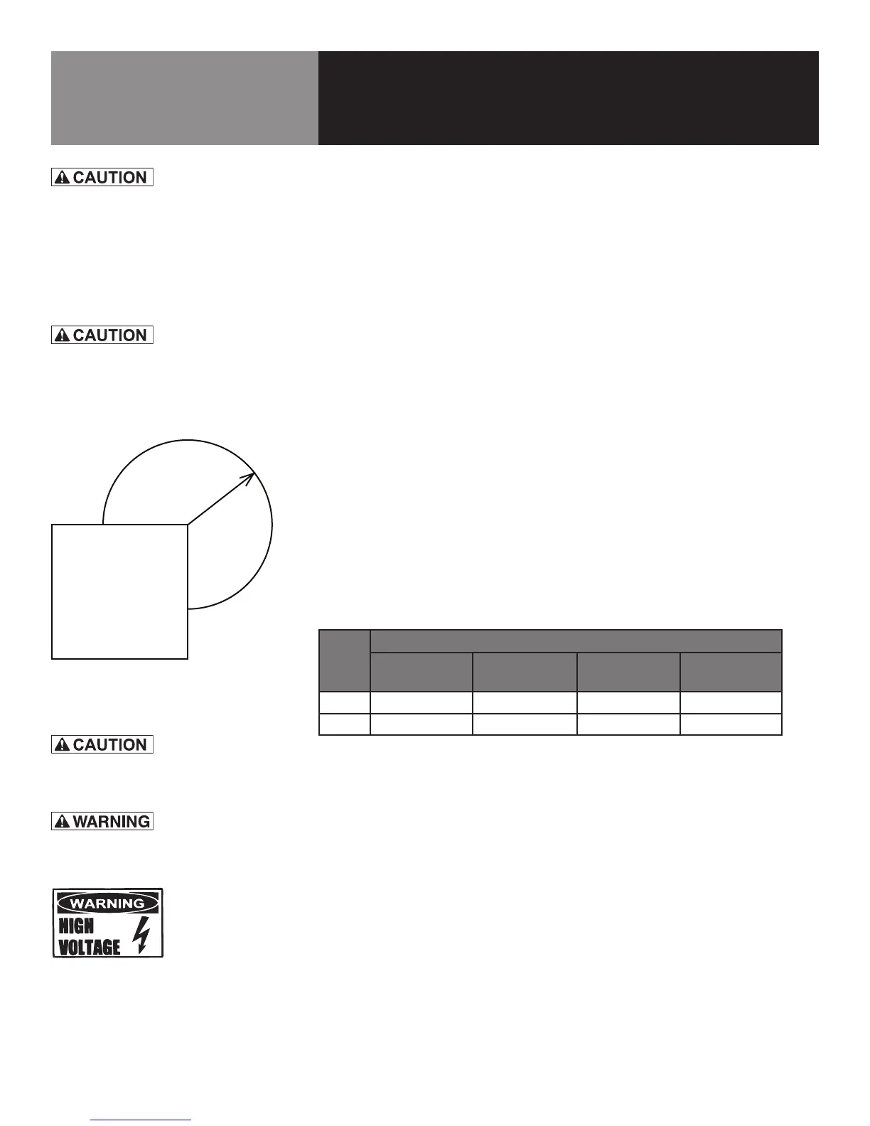
Steam Free Zone: The steamer can be damaged by steam from external sources. Do
not install the steamer over a steam venting drain. Ensure that steam is not present
in an area bounded by the footprint of the steamer and a circle 18 inches in radius
around the right rear corner of the steamer (See Diagram 7-1 at left).
ELECTRICAL SUPPLY CONNECTION
Provide service per local codes and/or the National Electrical Code should be observed
in accordance with ANSI/NFPA 70. AN ELECTRICAL GROUND IS REQUIRED. The
wiring diagram is located in the service compartment and in this manual. In Canada,
provide electrical service in accordance with the Canadian Electrical Code, CSA C22.2
Part 1 and/or local codes.
Electric current and power demands for each unit are as listed below.
Model Rated Current Demand Per Cavity
208/3 -
AMP/KW
208/1 -
AMP/KW
240/1 -
AMP/KW
208/3 -
AMP/KW
ST-4E 25.0/9 43.3/9 50/12 28.8/12
ST-6E 30/10.8 52/10.8 60/14 36.6/14
1. Panel Removal - Right Side
Open the wiring and control panel by removing the screws from the right
side panel. Remove and set aside. Save all screws.
2. Supply Voltage
The unit must be operated at the rated name plate voltage. The name plate
sticker can be found on the rear of the unit.
3. Phase Selection
Refer to steamer wiring diagram and element wiring on page 25 for wiring
information.
4. Terminal Block
The terminal block for incoming power is located at the back of the
18 -inch
radius
457
mm
THE UNIT MUST BE INSTALLED BY PERSONNEL
WHO ARE QUALIFIED TO WORK WITH
ELECTRICITY AND PLUMBING. IMPROPER
INSTALLATION CAN CAUSE INJURY TO
PERSONNEL AND/OR DAMAGE TO THE
EQUIPMENT. THE UNIT MUST BE INSTALLED IN
ACCORDANCE WITH APPLICABLE CODES.
DO NOT INSTALL THE UNIT WITH THE REAR
VENTS BLOCKED OR WITHIN 2 INCHES OF A
HEAT SOURCE SUCH AS A BRAISING PAN, DEEP
FAT FRYER, CHARBROILER OR KETTLE.
Diagram 7-1
EACH UNIT MUST HAVE A SEPARATE GROUND
WIRE FOR SAFE OPERATION.
TO AVOID DAMAGE OR PERSONAL INJURY,
FOLLOW THE WIRING DIAGRAM EXACTLY.
TOP VIEW
FRONT OF UNIT
STEAM
FREE
ZONE