www.longer3d.com info@longer3d.com
being damaged by the groove.
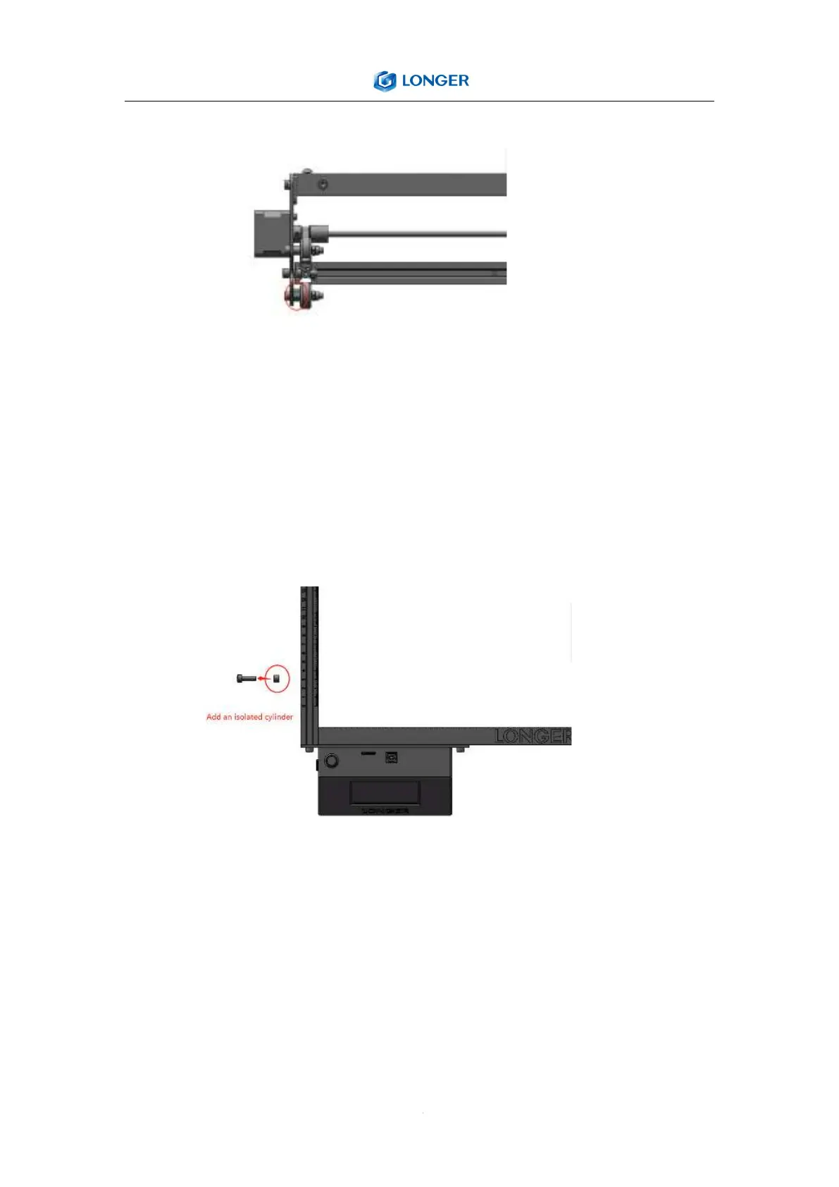
4. Preparation: Support feet x3, engraving machine control box, M5x20
hexagon socket cup head screw x1, M5x16 hexagon socket cup head screw
x7, M5x8 hexagon socket round head screw x1, M5 spring washer x8, nylon
isolation column (7*5* 6) x1.
4.1According to the figure, install the supporting foot, the control box of the
engraving machine, and the left profile limit screw in the corresponding position.
5. Preparation: timing belt x2, M5 trapezoidal nut x4, M5x6 hexagon socket
head screw x4.
5.1As shown in the figure, pass the timing belt through the roller and the
timing wheel, and use the square nut to fix the timing belt.The installation
method on the other side is the same.