11 12
Select pump head
and tubing refer to
the table of page 4
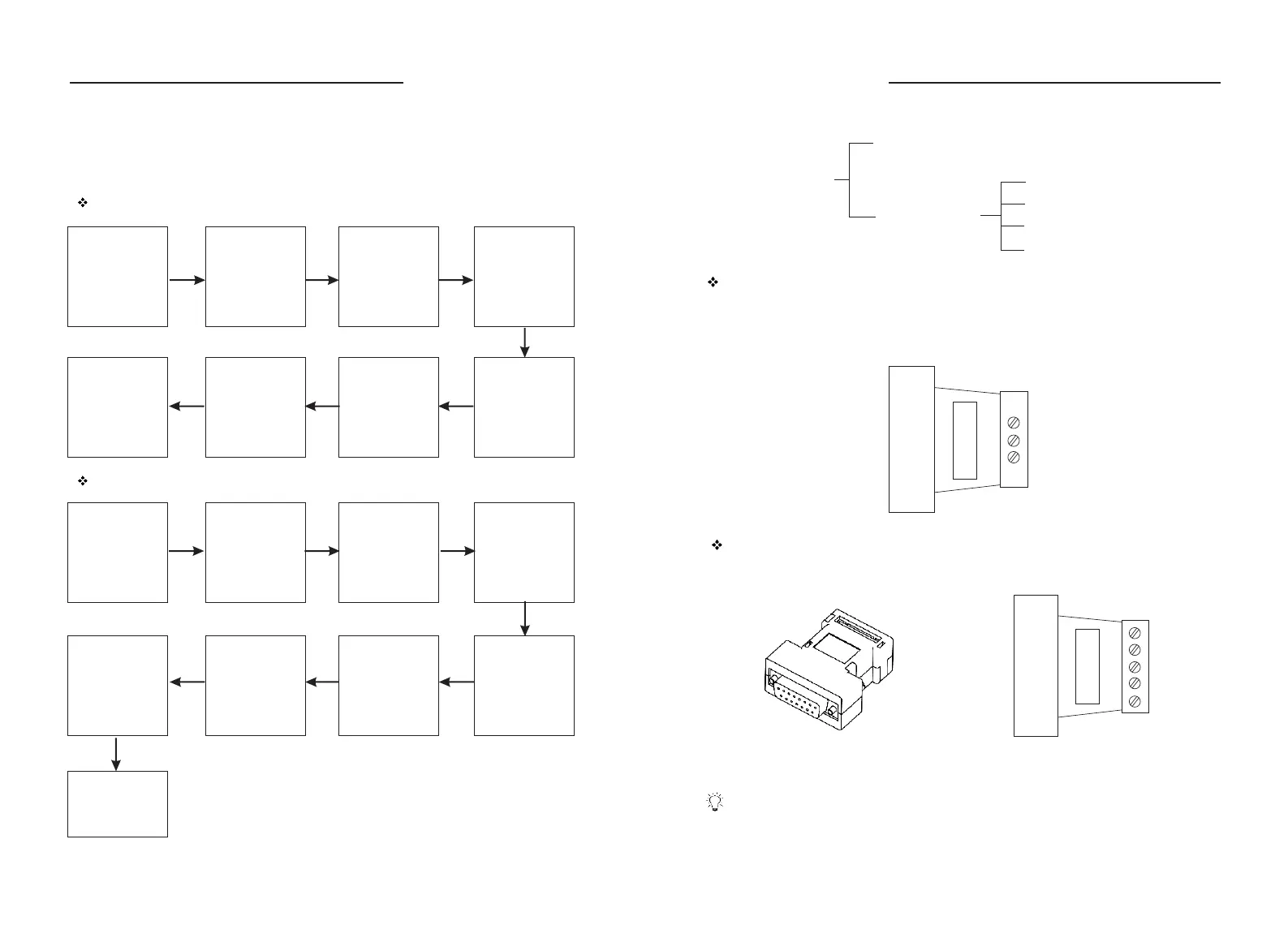
Dispensing mode operation procedure
Confirm the
volume to be
dispensed
Press Exit Key to
return to running
inter face
Operation Procedure
Before running the pump, select pump head and tubing refer to “Acceptable
Pump Head and Tubing (Table 1)”. Thick wall tubing is preferred for longer
service life.
Flow rates mode operation procedure
Confirm the flow
rates of the fluid
which need to be
pumped
Press Knob to
enter System
Setting inter face
to set pump head
and tubing
Enter Control
Mode interface to
select Flow Mode
Press Exit Key to
return to running
inter face, turn
Knob to select
needed flow rates
Press Knob to
enter calibration
selection inter face
and select
Flowrate when
calibration is
needed
Set Test Time,
press Start/Stop
to star t the pump.
Input the actual
volume
Press Exit Key to
return to running
inter face
Select pump
head and tubing
refer to the table
of page 4
Press Knob to
enter System
Setting inter face
to set pump head
and tubing
Set Back
Suction rpm
Enter control
mode interface
to select
Dispensing
Enter Dispense
Setting inter face
to set all the
dispensing
parameters.
Press Knob to
enter calibration
selection
inter face and
select Dispensing
when calibration
is needed
Press Start/Stop
to star t the pump.
Input the actual
volume
External Control Input
Analog Signal Input function
Communication Control
The pump can connect to control computer (computer, PLC, SCM) through
RS485 serial communication module (shown as below). Please contact Longer
Company for communication protocol.
COM
B
A
Set the “External Control” in “on” state. External control module is shown as below.
Five kinds of standard external control module need to be ordered separately
according to special requirements.
5
4
3
2
1
External Control Module
Analog Control
4 - 20 mA Speed Control
0 - 5 V Speed Control
0 - 10 V Speed Control
0 - 10 KHz Speed Control
External Control
DB15
Communication Control RS485
WT600-1F OPERATING MANUAL
WT600-1F OPERATING MANUAL