13 14
Terminal Definition of Standard External Control Module
Analog input in 4 - 20 mA, 0 - 5 V, 0 - 10 V external control
modules. Control the speed of the pump.
External control star t/stop input. When connected to COM, the
pump runs; When connected to high level, the pump stops.
External control cw/ccw input. When connected to COM, the pump
rotates clockwise; When connected to high level, the pump rotates
counter clockwise.
Analog ground (AGND) in 4 - 20 mA, 0 - 5 V, 0 - 10 V external
control modules;
Pulse input in pulse input external control modules. Control the
speed of the pump. 10 KHz is corresponding to the max.speed.
The COM of external control direction and star t/stop signal input;
It's also the COM of pulse signal input in pulse input external
control modules.
Terminal 1
Terminal 2
Terminal 3
Terminal 4
Terminal 5
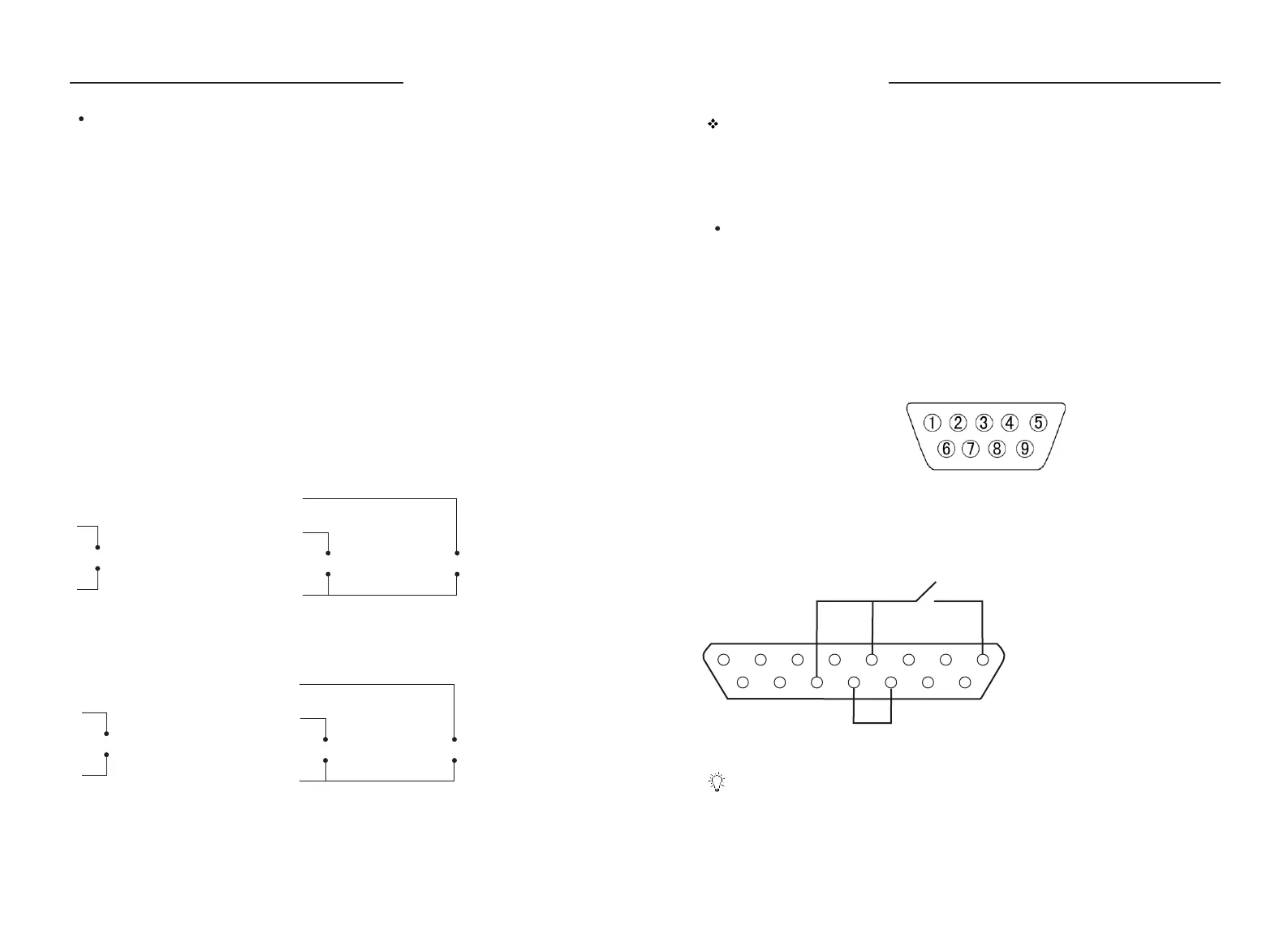
Pump is equipped with output por t in order to monitor the status of pump.
Please see below “External Control Output Por t Pins Diagram: DB9”. Output
signal adopts optoelectronic isolation circuit. A pull-up resistor and power
supply are needed when using.
Pins Definition
External Control Output
External Control Output Por t Pin Diagram: DB9
Footswitch Function
Connect Footswitch to r control Input Por t to control Star t/Stop of pump. emote
It can be set according to actual application.
Pin 1
Pin 2
Pin 8
Pin 4, 6, 7
Star t/Stop output. Pump outputs low level when it runs; pump
output high level when it stops.
Direction output. Pump output low level when it runs clock wise;
pump output high level when it runs count clock wise.
Pulse output, 0 - 600 rpm corresponding to 0 - 10 kHz.
COM
Footswitch is optional accessories. It can only control the start and stop of the
pump. The speed and direction of the pump are controlled by membrane keypad
and knob on the operation penal.
Connection Diagram for Footswitch
Shor t terminal 5 and 11; shor t
terminal 12 and 13; terminal 8
connects footswitch;
terminal 11 connects footswitch.
1 2 3 4 5 6 7 8
9 10 11 12 13 14 15
4 - 20 mA, 0 - 5V, 0 - 10V analog
input control the speed
0 - 5V, 0 - 10V, 4 - 20mA
External Control Input Module Connection Diagram
+
-
1
4
CC/CCW Signal
(5V TTL)
Star t/Stop Signal
(5V TTL)
+
-
3
5
+
-
2
0 - 10 kHz Pulse Signal Input Connection Diagram
0 - 10 kHz pulse input control
the speed
+
-
4
5
CC/CCW Signal
(5V TTL)
Star t/Stop Signal
(5V TTL)
+
-
3
5
+
-
2
WT600-1F OPERATING MANUAL
WT600-1F OPERATING MANUAL