6
5
VOL 0.25mL:
Copy 991:
YZ1515 ID 0.80
YZ1515
YZ2515
Select Tubing ID:
0.80 1.60 2.40
Ext Control :
ON OFF
Pump Address:
1
Menu Diagram
Running Interface
1.System Setting
2.Control Mode
3.Disp Setting
4.Calibration
1. Pump head Tube&
YZ1515 ID 0.80
2.Ext Cont. ON:
3.Address 1:
4.Footswitch G:
5.Back T. 1 2:."
Flowrate
Dispensing
Disp Vol 2.02mL:
Copy No. 10:
Flow 2.043mL/min:
Pause T. 1.0:"
Flowrate
Dispensing
1.System Setting
2.Control Mode
3.Disp Setting
4.Calibration
1.System Setting
2.Control Mode
1. Pump head Tube&
1.System Setting
2.Control Mode
2.Ext Cont. ON:
3.Address 1:
1.System Setting
2.Control Mode
2.Ext Cont. ON:
3.Address 1:
Pump Head Installation
The pump head is mounted on drive before the pump leaves the factory. Follow
below procedure for changing another pump head.
Loose the two M4 screws which connect the pump head and the drive.
Dismantle the pump head slightly.
Insert the flat end of the pump head's shaft to the slot of drive's coupling.
Make the location hole of the pump head match the location pin of the drive.
Insert the two mounting screws into the mounting holes of the pump head.
Then tighten the mounting screws to connecting hole of drive. (For more
information, please refer to pump head's operation manual)
Turn off the power before changing the pump head.
Note:
System Setting:
All the setting can not be done when pump is running.
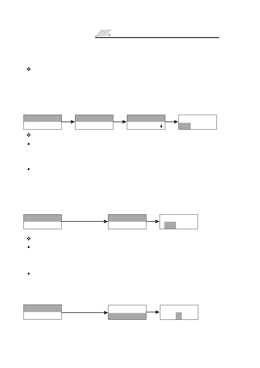
Pump head and tubing setting
Press the to enter interface, press again to enter
submenu of , then press again the pump will show all
the suitable pump head, turn to select needed pump head, press the
again to confirm the selection of pump head and the pump will show all the
suitable tubing, turn to select needed tubing and press to confirm or
press to return to previous menu.
Knob System Setting Knob
Pump Head & Tube Knob
Knob Knob
Knob Knob
Exit Key
External Control
Set the pump to enable the or not.
On: Enable
Off: Disable
Set the
Press and turn to highlight the external control line. Press to enter
next interface, turn to select or then press to confirm or press
to cancel the selection and return to previous menu.
In external control mode, the status of external control can be changed when the
pump stops.
External Control
External Control
External Control
External Control
Knob Knob
Knob On Off Knob
Exit Key
Press and turn Knob
Press and turn Knob
Address:
When control computer controls many pumps through RS485 interface, it must
identify each pump's I. D. This pump I.D. should be unique. It's the identification
of this pump. Maximum 30 pieces BT100-1F can be controlled through RS485 at
the same time.
Setting of each pump
Press and turn the to highlight the line. Press again to enter
next interface, turn Knob to select , and then press to confirm or
press Exit Key to cancel the selection and return to previous menu.
Address
Knob Address Knob
Pump ID Knob
1.
2.
3.
BT100-1F OPERATING MANUAL
BT100-1F OPERATING MANUAL