6
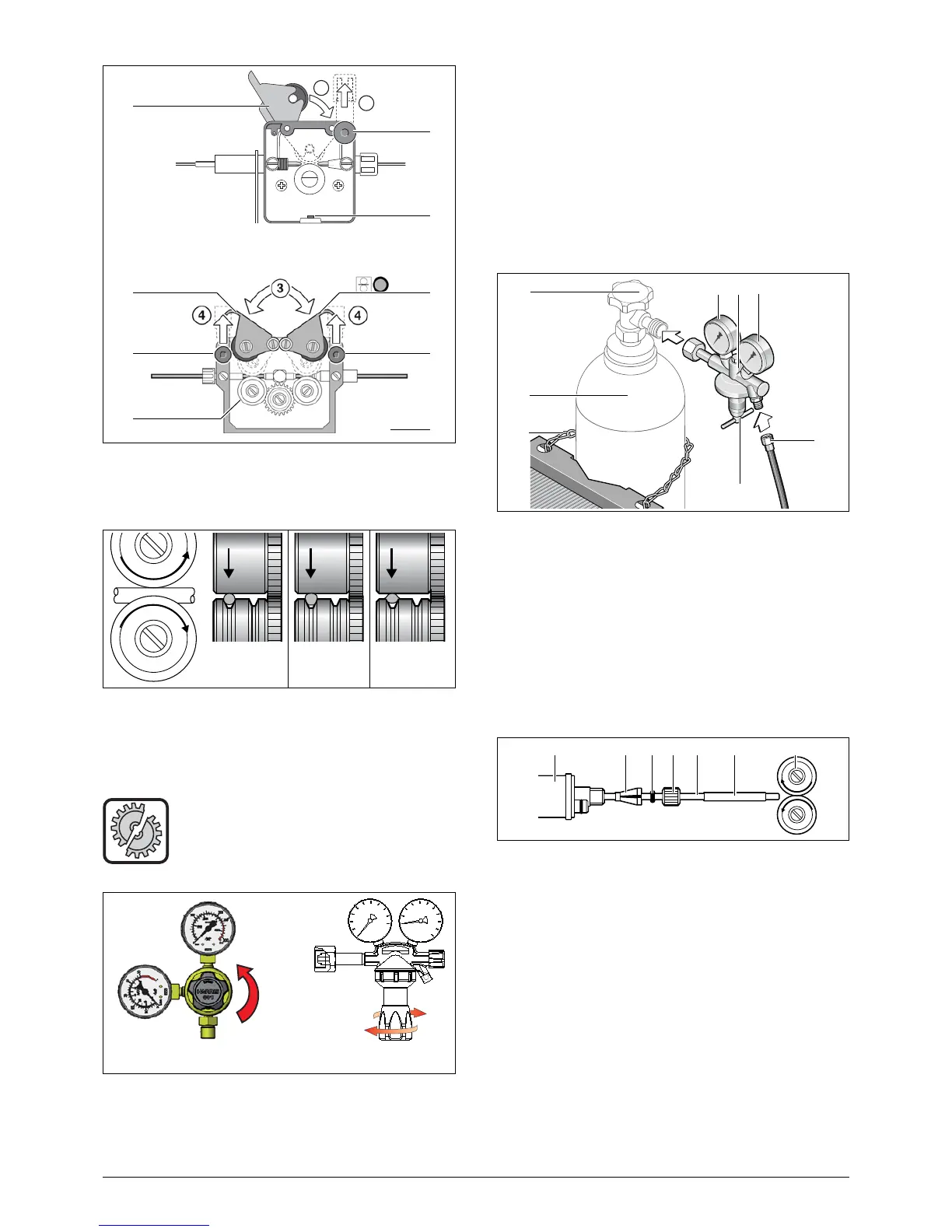
Switch on machine at main switch 34, stretch torch cable and
press buttons 22 on operating panel. Adjust the pressure at
the modulation screws 20 that the wire-feed rolls 19 even still
are turning by holding the wire coil. The wire should not be
clamped or deformed.
Hold down button 22 until wire projects about 20 mm from
torch neck.
Screw in the contact tip corresponding to the wirediameter
into the torch 3 and cut off the sticked out wire end.
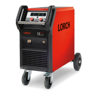
How to connect the gas cylinder
Before opening the bottle the adjustment
screw 28 at the housing must be relieved, it
means, turned to the left, otherwise the
pressure-reducing vale could be damaged.
Put the gas cylinder 2 on the provided place at the back of the
machine and protect against falling by fastening the chain 27.
Open the gas valve 26 several times to blow out possible dirt
particles.
Turn the adjustment screw 28 of the pressure reducer 1 com-
pletely to the left.
Connect the pressure reducer 1 at the gas cylinder 2.
Connect the gas hose 23 at the pressure reducer. Open the
gascylinder and adjust the gas flow at the set screw 28 of the
pressure reducer while pressing the torch button.
The quantity will be shown at the flowmeter 24. This should
be approx. wire diameter x 10 l/min. The content of the cylin
-
der is shown by the contentmanometer 25.
How to modify the machine for aluminium
welding
Change the wire roll to a aluminium wire roll.
Change the steel-torch against an aluminiumtorch or resp.
change the wire liner against a teflon liner.
Remove the capillary tube 33 at the central connection.
Cut the teflon liner close to the end of the wire-feeding roll and
pull the brasstube over the teflon liner with the corresponding
length for stabilising it.
Fasten the torch and thread in the wire electrode.
)
The art.no. of the parts depends on the torch and wire-
diameter. Please see at the torch spare list.
11 centralconnection
29 nipple for 4.0 mm and 4.7 external diameter
30 o-ring 3.5x1.5 mm to prevent gas outlet
31 nut
32 teflon and plastic liner
33 sustainpipe for teflon and plastic liner with 4 mm exter-
nal diameter it substitute the capillary pipe in the central
connection.
At 4.7 mm no sustainpipe is required.
19 wire-feed roll