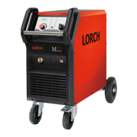
Do you have a question about the LORCH MicorMIG 350 and is the answer not in the manual?
Mandatory safety measures for operation, maintenance, and qualified personnel.
Explanation of the electronic welding power source inverter technology.
Details on new welding programs and changes to the synergic selection panel.
Functions of the DRV03/DRV13 board, including LED status and measuring points.
Functions, LED status, and measuring points for DRV05/DRV15 boards.
Functions, LED status, and measuring points for DRV07/DRV17 boards.
Description of initial DRV version and 'S' version features like power-up stabilization.
Details on 'R17' version features: bus voltage balancing and overvoltage reset.
Description of 'R32' version features: bus voltage measuring modification.
Information on the change to new DRV boards and compatibility requirements.
Table listing old DRV boards, their replacements, and new part numbers.
Core functions of the MAPRO04 board for machine control.
Note on SF18 replacement with SF23 due to unavailability.
How the machine monitors bus voltage and related error codes (E02, E22, E33).
Explanation of PE monitoring feature and associated error E04-01.
Description of the water monitoring system using a self-heating sensor.
Schematic of water monitoring and error E05 for no water flow detected.
How output voltage is monitored and related error codes (E06, E12, E18).
How welding current is monitored via DSP and FPGA, and error codes E15.
How the wire feed motor is driven, monitored, and error E08.
How the machine configuration is read and compared, and error E30.
Details on configuration resistors and DIP switch settings for DRV boards.
Monitoring of input current and related error codes E32.
Description of the remote control interface and its connection.
Explanation of signals, pins, and functions for the LorchNet-Remote.
Description of the LorchNet-Connect adapter box for PC connectivity.
Diagram showing how to connect a PC to the MicorMIG via LorchNet Connect.
Methods for reading machine data: NFC and QR-code.
Step-by-step guide for reading machine data via NFC using a smartphone.
Procedure for reading machine data via QR-code using a smartphone.
Error codes E01, E02, E04, E05, E06 related to temperature, voltage, and PE.
Error codes E07, E08, E12 related to EEPROM, wire feed motor, and power unit startup.
Error codes E13, E14, E15, E18, E22, E25 related to supply, offset, overload, OCV.
Error codes E33, E34, E41 related to bus voltage, fan, and mains loss.
Error codes E27, E30, E31, E32 related to configuration, communication, and current.
Error codes E48 related to demo mode and CAN bus connection issues.
| Input Voltage | 3 x 400 V |
|---|---|
| Duty Cycle | 60% at 350 A |
| Weight | 32 kg |
| Protection class | IP23 |
| Rated duty cycle at 40°C | 60% at 350 A |
| Welding process | MIG/MAG |
| Power supply voltage | 400 V |
