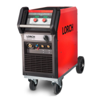
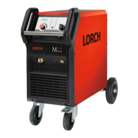
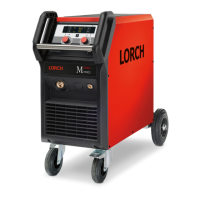
Do you have a question about the LORCH MicorMIG 300 and is the answer not in the manual?
Defines user responsibilities and the need for qualified personnel for machine operation.
Specifies procedures and conditions for machine testing as per IEC 60974-4.
Lists the primary roles of the NEFI02 main filter board.
Lists the key functions of the DRV03/DRV13 primary driver boards.
Outlines the main functions of the DRV05/DRV15 primary driver boards.
Lists the main functions of the DRV07/DRV17 primary driver boards.
Information on compatibility between old DRV0x and new DRV1x boards.
Details main control logic functions and shows the MAPRO04 board.
Lists functions and explains LEDs on the DMR-RT3 wire feed control board.
Details functions for Push-Pull torches and NanoFeeder.
Electrical diagram illustrating bus voltage monitoring.
Electrical diagram for monitoring output voltage.
Details on configuration resistors for the DRV13 board.
Details on configuration resistors for the DRV15 board.
Details on configuration resistors for the DRV17 board.
Input current monitoring schematic for MicorMIG 300/350 models.
Input current monitoring schematic for MicorMIG 400 model.
Input current monitoring schematic for MicorMIG 500 model.
Electrical diagram for the LorchNet-Remote interface.
Steps for measuring resistance on the CAN bus for diagnostic purposes.
Lists information messages, their causes, and relevant remarks.
A detailed list of error codes, their causes, and remarks.
| Output Current Range | 25 A - 300 A |
|---|---|
| Welding process | MIG/MAG |
| Protection class | IP23 |
| Insulation class | F |
| Wire Diameter Range | 0.8 mm - 1.2 mm |
| Input Voltage | 400 V |
| Cooling | Fan |
| Wire Feed Speed Range | 1 m/min - 25 m/min |
