page 5
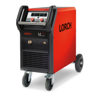
The MicorBoost Inverter Principle
A welding inverter is a electronically controlled welding power source. At conventional transformer based ma-
chines, the mains voltage with 50/60 Hz is directly switched to the welding transformer. At a welding inverter the
mains voltage is rectied rst and with electronic power switches (MOSFETs or IGBTs) chopped into a much
higher frequency, to drive the transformer. At conventional inverters this is a xed frequency (e.g. 80kHz) at
MICOR machines the frequency is variabel (up to 200kHz), because the frequency is also used for controling the
welding process. Driving the transformer, the primary side is a serial resonant circuit (primary transformer coil in
series with a capacitor) and the secondary side is a parallel resonant circuit, so that the control has an additional
inuence on the output voltage by shifting the frequency. With this principle an almost ideal output characteristic
can be realized.
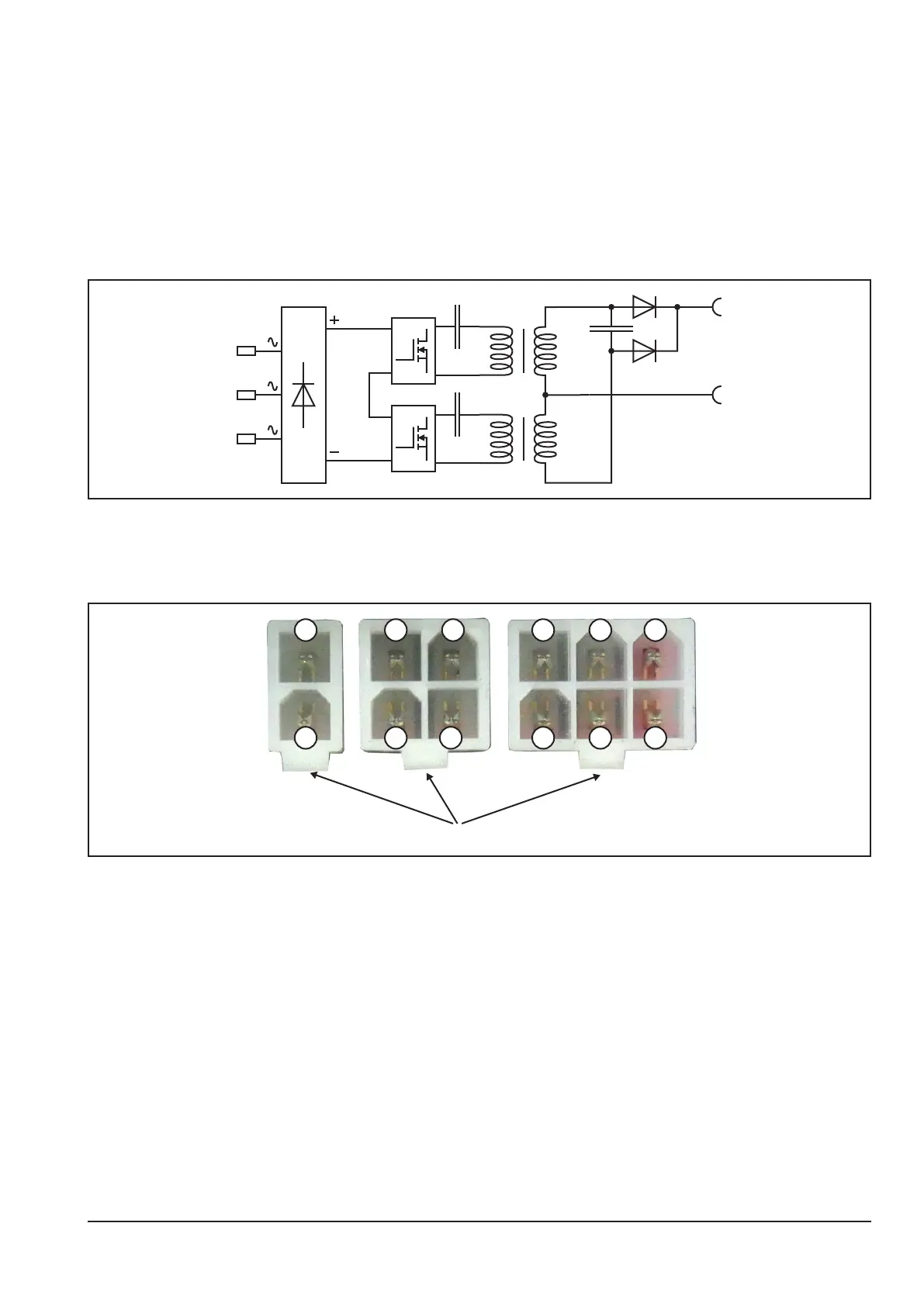
Counting pins for Minit and Microt connectors
The way of reading the pin numbers on the Minit- and Microt-connectors is done always in the same way: when
looking from the top onto the connector, pin no.1 is alway on the far left, opposite to the clip.
Clip
654
32121
43
1
2