EasyManuals Logo

LORCH V40 User Manual

LORCH V40
48 pages
To Next Page IconTo Next Page
To Previous Page IconTo Previous Page
Page #15 background imageLoading...
Page #15 background image
page 15
Overview connectors pc-board DCDRV
connector designation
X1 connector to pc-board DP-MAPRO
X2 connector current sensor and pc-board PRWUP
X3 connector temperature sensor
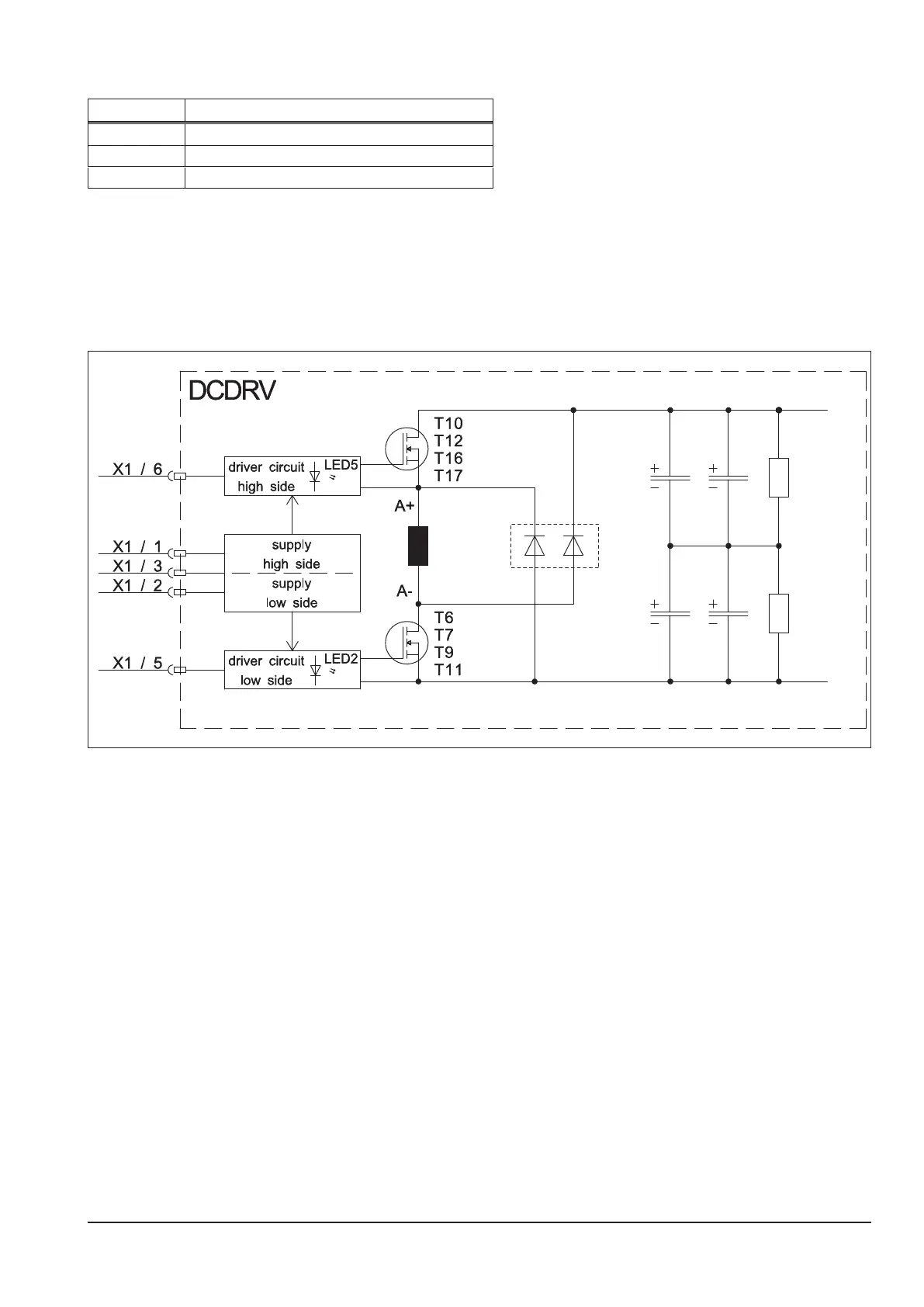
Primary Driver
The pc-baord DCDRV is the primary driver board for the transformer. It is a classical half bridge design. The sup-
ply is provided via pins 1, 2 and 3 of the at ribbon cable and the PWM signals (PWM = Pulse Width Modulation)
for driving the MOSFETs are at pin 5 (low side) and pin 6 (high side).
Schematic
+Ubus
-Ubus

Questions and Answers:

Question and Answer IconNeed help?

Do you have a question about the LORCH V40 and is the answer not in the manual?

LORCH V40 Specifications

General IconGeneral
BrandLORCH
ModelV40
CategoryWelding System
LanguageEnglish

Related product manuals