EasyManua.ls Logo

LOVATO ELECTRIC DCRL5 User Manual

LOVATO ELECTRIC DCRL5
19 pages
To Next Page IconTo Next Page
Page #1 background imageLoading...
Page #1 background image
Doc: I377DEGB03_14.doc 04/03/2014 p. 1 / 19
DCRL3 – DCRL5 DCRL3 – DCRL5
Automatischer Automatic Power Factor
Leistungsfaktorregler Controller
BETRIEBSANLEITUNG INSTRUCTIONS MANUAL
● Vor jedem Eingriff am Instrument die Spannungszufuhr zu den Messeingängen trennen und
die Stromwandler kurzschließen
Bei zweckwidrigem Gebrauch der Vorrichtung übernimmt der Hersteller keine Haftung für die
elektrische Sicherheit.
Die in dieser Broschüre beschriebenen Produkte können jederzeit weiterentwickelt und
geändert werden. Die im Katalog enthaltenen Beschreibungen und Daten sind daher
unverbindlich und ohne Gewähr.
● In die elektrische Anlage des Gebäudes ist ein Ausschalter oder Trennschalter einzubauen.
Dieser muss sich in unmittelbarer Nähe
des Geräts befinden und vom Bediener leicht zugänglich
sein. Er muss als Trennvorrichtung für das Gerät gekennzeichnet sein: IEC/ EN 61010-1 §
6.11.2.1.
● Das Instrument mit einem weichen Tuch reinigen, keine Scheuermittel, Flüssigreiniger oder
Lösungsmittel verwenden.
● Before any maintenance operation on the device, remove all the voltages from measuring
and supply inputs and short-circuit the CT input terminals.
● Products illustrated herein are subject to alteration and changes without prior notice.
● Technical data and descriptions in the documentation are accurate, to the best of our
knowledge, but no liabilities for errors, omissions or contingencies arising there from are
accepted.
● A circuit breaker must be included in the electrical installation of the building. It must be
installed close by the equipment and within easy reach of the operator.
It must be marked as the disconnecting device of the equipment:
IEC /EN 61010-1 § 6.11.2.1.
Clean the instrument with a soft dry cloth; do not use abrasives, liquid detergents or
solvents
.
Inhalt
Seite
Vorwort
1
Beschreibung
2
Funktion der vorderen Tasten
2
Displayanzeigen
2
Betriebsarten
3
Messungen
4
Tastatursperre
5
Erweiterbarkeit
5
Programmierschnittstelle IR
6
Parametereinstellung vom PC
6
Parametereinstellung von Tablet oder Smartphone
6
Parametereinstellung vom frontseitigen Bedienpanel
6
Schnelleinstellung Stromwandler
7
Parametertabelle
8
Alarme
12
Beschreibung der Alarme
12
Default Alarmeigenschaften
13
Befehlsmenü
14
Verwendung Dongle CX02
15
Installation
16
Anschlusspläne
16
Klemmenanordnung
18
Mechanische Abmessungen und Bohrung der Platte
18
Technische Merkmale
18
Chronik der Revisionen der Betriebsanleitung
19
Index
Page
Introduction
1
Description
2
Keyboard functions
2
Display indications
2
Operating modes
3
Measures
4
Keypad lock
5
Expandability
5
IR programming port
6
Parameter setting through PC
6
Parameter setting through tablets or Smarphones
6
Setting of parameters (setup) from front panel
6
Rapid CT setup
7
Parameter table
8
Alarms
12
Alarm description
12
Default alarm properties
13
Command menu
14
CX02 dongle usage
15
Installation
16
Wiring diagrams
16
Terminals position
18
Mechanical dimensions and Panel cutout
18
Technical carachteristics
18
Manual revision history
19
Vorwort
Bei Entwicklung des automatischen Leistungsfaktorreglers DCRL wurde
dem Stand der Technik der erforderlichen Funktionen für die
Anwendungen der Leistungsfaktorkorrektur Rechnung getragen. Der
DCRL hat ein eigenes, extrem kompaktes Gehäuse und vereint das
moderne Design der Frontblende mit der praktischen Überwachung und
der Möglichkeit der Erweiterung an der Rückseite, wo ein Modul der Serie
EXP eingesetzt werden kann. Das LCD-Display bietet eine
leichtverständliche und intuitive Benutzeroberfläche.
state-of-the-art functions for power factor compensation applications.
Built with dedicated components and extremely compact, the DCRL
and the possibility of expansion from the rear, where one EXP series
module can be slotted. The LCD screen provides a clear and intuitive
user interface.
I377 DE GB 0314
ACHTUNG!
● Dieses Handbuch vor Gebrauch und Installation aufmerksam lesen.
Zur Vermeidung von Personen- und Sachschäden dürfen diese Geräte
nur von qualifiziertem Fachpersonal und unter Befolgung der einschlägigen
Vorschriften installiert werden.
WARNING!
x Carefully read the manual before the installation or use.
x This equipment is to be installed by qualified personnel, complying to
current standards, to avoid damages or safety hazards.
GB
DE

Other manuals for LOVATO ELECTRIC DCRL5

Question and Answer IconNeed help?

Do you have a question about the LOVATO ELECTRIC DCRL5 and is the answer not in the manual?

LOVATO ELECTRIC DCRL5 Specifications

General IconGeneral
CategoryController
Frequency50/60 Hz
MountingDIN rail
Protection degreeIP20
Number of Outputs1
Output TypeRelay
Mounting TypeDIN rail
Operating temperature-20 to 60 °C
Contact Rating5 A at 250 VAC
Storage Temperature-20°C to +70°C

Summary

Introduction

Introduction

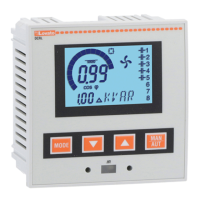
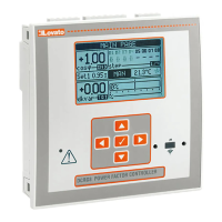
Unit introduction and user interface overview.

General Safety Warnings

Product Description

Description

Overview of the automatic power factor controller features and versions.

Front Keyboard Functions

Explains the functions of the MODE, ▲, ▼, and MAN-AUT keys.

Display Indications

Describes the main display elements and their meanings.

Operating Modes

TEST Mode

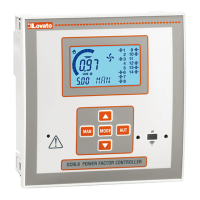
Allows manual activation of relay outputs for wiring verification.

MAN and AUT Modes

Details how to switch between manual and automatic operation modes.

MAN Mode Operation

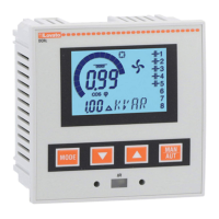
Manual control of capacitor steps for connection or disconnection.

AUT Mode Operation

Automatic calculation of steps for optimal cosphi based on various parameters.

Measurements and Readings

Available Measurements

Lists available measurements and how to navigate them via the MODE key.

Keypad Lock and Expandability

Keypad Lock

Prevents accidental changes to operating parameters.

Expandability Features

Describes how to expand the DCRL with EXP series modules.

Programming and Configuration

IR Programming Port

Configuration via optical port, USB, or WiFi dongles for safe and efficient operation.

Parameter Setting with PC

Using DCRG Remote control software for parameter transfer.

Parameter Setting from Front Panel

Accessing and navigating the unit's programming menu.

Parameter Management

Parameter Table Navigation

Lists available submenus like Base, Advanced, Alarm, Command, and Custom.

Rapid CT Setup

Base Menu Parameters

Base Menu Parameter Details

Details parameters P.01 to P.20, including description, range, and factory default.

Advanced Menu Parameters

Advanced Menu Parameter Details

Details parameters P.21 to P.29 for advanced settings and configuration.

Parameter Details (P.30-P.53)

Parameter Details (P.30-P.53)

Covers disconnection sensitivity, fan control, voltage/current thresholds, and communication settings.

Alarm Configuration and Menu

Alarm Menu Configuration

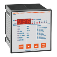
Configuration of alarm triggers, delays, and behavior.

Alarm Descriptions

Alarm Descriptions (A01-A09)

Explains various alarm codes (A01-A09) and their meanings.

Default Alarm Properties

Default Alarm Properties

Lists default settings for alarm activation, relay, disconnection, and delay.

Commands Menu Operations

Commands Menu Operations

Provides commands for resetting values, backups, and factory defaults.

CX02 Dongle Usage

Installation and Wiring

Installation Procedures

Guides for flush-mount installation and panel fitting.

Standard Three-phase Wiring

Wiring configuration for standard three-phase applications.

Single-phase and MV Wiring

Single-phase Wiring

Wiring configuration for single-phase compensation systems.

MV Wiring Configuration

Configuration for medium voltage applications with measurement and compensation.

Device Physical and Technical Specifications

Terminal Layout

Shows the terminal arrangement for DCRL3 and DCRL5 units.

Mechanical Dimensions and Panel Cutout

Provides physical dimensions and panel cutout specifications.

Technical Characteristics

Lists electrical and environmental specifications of the device.

Manual Revision History

Related product manuals