Doc: I378RUGB05_16.doc 10/02/2014 p. 1 / 43
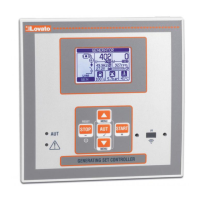
RGK600 - RGK601 RGK600 - RGK601
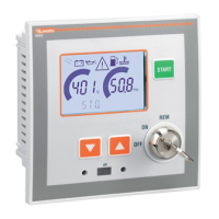
RGK600SA - RGK601SA RGK600SA - RGK601SA
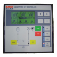
RGK610 RGK610
Блок управления Generating set
генераторными установками controller
РУКОВОДСТВО ПО ЭКСПЛУАТАЦИИ INSTRUCTIONS MANUAL
● Перед тем как выполнять какие-либо работы на приборе, отключите напряжение с
клемм питания и измерения и замкните накоротко между собой клеммы
трансформаторов тока.
● Изготовитель не несет ответственность за обеспечение электробезопасности в
случае ненадлежащего использования прибора.
● Изделия, описанные в настоящем документе, в любой момент могут подвергнуться
изменениям
или усовершенствованиям. Поэтому описания и каталожные данные не
могут считаться действительными для целей контрактов.
● Выключатель или размыкатель должен входить в состав системы
электроснабжения здания. Прибор должен устанавливаться в шкафу со свободным
доступом пользователя. Маркировка в соответствии с: IEC/ EN 61010-1 § 6.11.2.1.
● Используйте для чистки прибора мягкую тряпку; не применяйте абразивные
средства, жидкие
моющие средства или растворители.
● Before any maintenance operation on the device, remove all the voltages from measuring
and supply inputs and short-circuit the CT input terminals.
● Products illustrated herein are subject to alteration and changes without prior notice.
● Technical data and descriptions in the documentation are accurate, to the best of our
knowledge, but no liabilities for errors, omissions or contingencies arising there from are
accepted.
● A circuit breaker must be included in the electrical installation of the building. It must be
installed close by the equipment and within easy reach of the operator.
It must be marked as the disconnecting device of the equipment:
IEC /EN 61010-1 § 6.11.2.1.
● Clean the instrument with a soft dry cloth; do not use abrasives, liquid detergents or
solvents
.
Оглавление Страница
Введение 2
Описание 2
Функции клавиш, расположенных на передней панели
прибора
3
Светодиоды на передней панели 3
Режимы работы 3
Подача напряжения на прибор 4
Главное меню 5
Доступ с помощью пароля 5
Таблица страниц дисплея 6
Резистивные датчики уровня топлива, температуры,
давления
8
Удаленный запуск на моделях ..S
9
Входы, выходы, внутренние переменные, счетчики 9
Пороговые значения (LIMx) 9
Дистанционно управляемые переменные (REMx) 10
варийные сигналы, программируемые пользователем
(UAx)
10
втоматическое тестирование 11
Спящий режим 11
CAN bus 11
ИК порт для программирования 13
Настройка параметров с ПК 13
Настройка параметров с использованием клавиш на
передней панели
13
Таблица параметров 15
варийные сигналы 28
Свойства аварийных сигналов 29
Таблица аварийных сигналов 29
Описание аварийных сигналов 31
Таблица функций входов 33
Таблица функций выходов 34
Меню команд 35
Установка 36
Схемы соединения 38
Расположение клемм 41
Механические размеры прибора и размеры ниши для
встраивания
41
Технические характеристики 40
Хронология изменений руководства 41
Index
Page
Introduction
2
Description
2
Front buttons functions
3
Front LED indication
3
Operating modes
3
Power-up
4
Main menu
5
Password access
5
Table of display pages
6
Resistive sensors for fuel, temperature and pressure
8
Remote
start for …SA versions
9
Inputs, outputs, internal variables, counters 9
Limit thresholds (LIMx)
9
Remote-controlled variables (REMx) 10
User alarms (UAx)
10
utomatic test
11
Sleep mode
11
CAN bus
11
IR programming port
13
Parameter setting via PC
13
Parameters setting (setup) from front panel 13
Parameter table
15
larms
28
larm properties
29
larm table
29
larm description
31
Input function table
33
Output function table
34
Command menu
35
Installation
36
Wiring diagrams
38
Terminal position
41
Mechanical dimensions and panel cutout 41
Technical characteristics
40
Manual revision history
41
ВНИМАНИЕ!!!
● Перед тем как приступать к установке и использованию прибора,
внимательно прочитайте настоящее руководство.
● Установка данных приборов должна осуществляться
квалифицированным персоналом с соблюдением норм техники
безопасности во избежание травм или материального ущерба.
WARNING!
Carefully read the manual before the installation or use.
This equipment is to be installed by qualified personnel, complying to
current standards, to avoid damages or safety hazards.
RU