I581 GB I 05 18 31100420
11
G
B
4 COMMISSIONING
4.1 IMPORTANT NOTES
Incorrect settings during commissioning may cause unexpected and dangerous motor and system movements.
Possible consequence: death, severe injuries or damage to property
– Clear hazardous area.
– Observe safety instructions and safety clearances.
4.2 BEFORE INITIAL SWITCH-ON
Prevent injury to persons and damage to property. Check the following before switching on the mains voltage:
– Is the wiring complete and correct?
– Are there no short circuits and earth faults?
– Is the motor circuit configuration (star/delta) adapted to the output voltage of the drive?
– Is the motor connected in-phase (direction of rotation)?
– Does the "emergency stop" function of the entire plant operate correctly?
4.3 INITIAL SWITCH-ON / FUNCTIONAL TEST WITH TERMINAL CONTROL
Target: achieve rotation of the motor connected to the drive as quickly as possible. Requirements:
– The connected motor matches the drive in terms of power.
– The parameter settings comply with the delivery status (LOVATO setting).
1. Preparation:
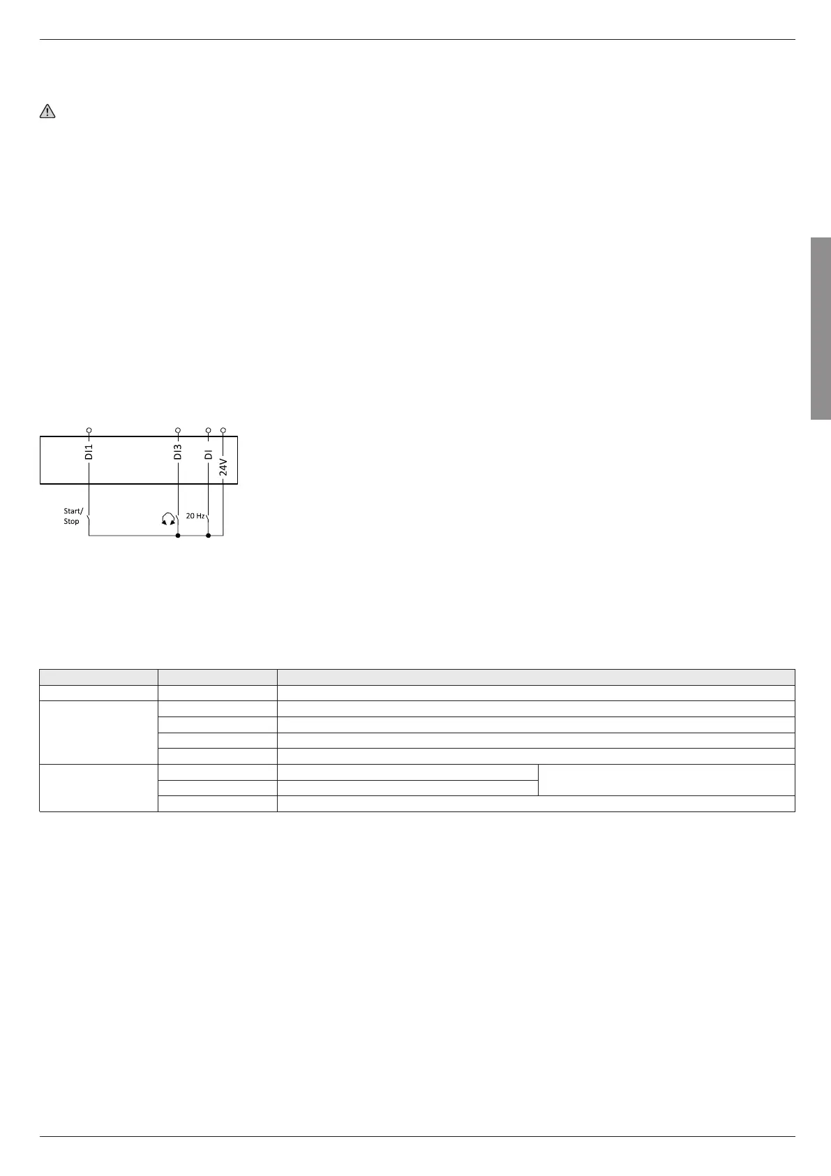
1. Wiring of power terminals. (Chapter 3.3 Electrical installation)
2. Wire digital inputs X3/DI1 (start/stop), X3/DI3 (reversal of rotation direction), and X3/DI4 (preset frequency setpoint 20 Hz).
3. Do not connect terminal X3/AI1 (analog setpoint selection) or connect it to GND.
2. Switch on mains and check readiness for operation:
1. Switch on mains voltage.
2. Observe LED status displays "RDY" and "ERR" on the front of the drive:
a) If the blue "RDY" LED is blinking and the red "ERR" LED is off, the drive is ready for operation. The controller is inhibited.
You can now start the drive.
b) If the red "ERR" LED is lit permanently, a fault is pending.
Eliminate the fault before you carry on with the functional test.
LED STATUS DISPLAYS
"RDY" LED (blue) "ERR" LED (red) Status/meaning
off off No supply voltage.
blinking (2 Hz) off Drive inhibited.
lit every 1.5 s for a short time Drive inhibited, no DC-bus voltage.
blinking fast (4 Hz) Drive inhibited, warning active.
on Drive inhibited, fault active.
on off Drive enabled. The drive rotates according to the setpoint specified.
blinking fast (4 Hz) Drive enabled, warning active.
blinking (1 Hz) Drive enabled, quick stop as response to a fault active.
 Loading...