I511 GB I 09 17 31100346
G
B
12
CODE COMMAND ACCESS LEVEL DESCRIPTION
C.01 RESET HI-LO User / Advanced Resets the HI and LO values of all measurements
C.02 RESET MAX DEMAND User / Advanced Resets Max Demand values for all measurements
C.03 RESET PARTIAL ENERGY METERS User / Advanced Resets partial energy meters
C.04 RESET PARTIAL HOUR COUNTER User / Advanced Resets partial hour counters
C.06 RESET TARIFFS User / Advanced Resets energy meters with tariff 1 and 2
C.07 RESET ALARMS User / Advanced Resets alarms with latch
C.08 RESET LIMITS User / Advanced Resets limit thresholds with latch
C.11 RESET TOTAL ENERGY METER Advanced Resets total and partial energy meters
C.12 RESET TOTAL HOUR COUNTERS Advanced Resets total hour counters
C.13 PARAMETERS TO DEFAULT Advanced Restores all settings to factory default values
C.14 PARAMETER BACKUP Advanced Saves a backup copy of all setup parameters
C.15 PARAMETERS RESTORE Advanced Reloads the settings from the backup copy
C.16 WIRING TEST Advanced Runs the test to check that the DME D332 is connected correctly - See wiring test
COMMANDS MENU
– The commands menu permits the execution of occasional operations such as resetting measurements, meters, counter, etc.
– If the Advanced-level password has been entered, the commands menu can also be used to perform some automatic operations that are useful for configuring the instrument.
– The following table lists indicates the functions available in the commands menu, divided by access level required.
– Once the required command has been selected, press to execute it. The device will prompt for a confirmation. Pressing again will execute the command.
– To cancel the command execution, press MENU.
– To quit the commands menu, press
and
simultaneously.
WIRING TEST
– The wiring test permits verification of the correct installation of the energy meter.
– In order to run the test, the energy meter must be connected to an active system with the following conditions:
• Three-phase system with all phases present (V > 187VAC PH-N)
• Minimum current flow in each phase > 1% of the CT full scale set
• Positive flow of energies (i.e. a normal system where the inductive load draws power from the supply).
– To launch the test execution, enter the commands menu and select command C.16, according to the instructions in the Commands Menu section.
– The test allows to verify the following points:
• Reading of the three voltages
• Phase sequence
• Voltage unbalance
• Reverse polarity of one or more CTs
• Mismatch between voltage/current phases
– If the test does not succeeds, the display shows the reason of the failure.
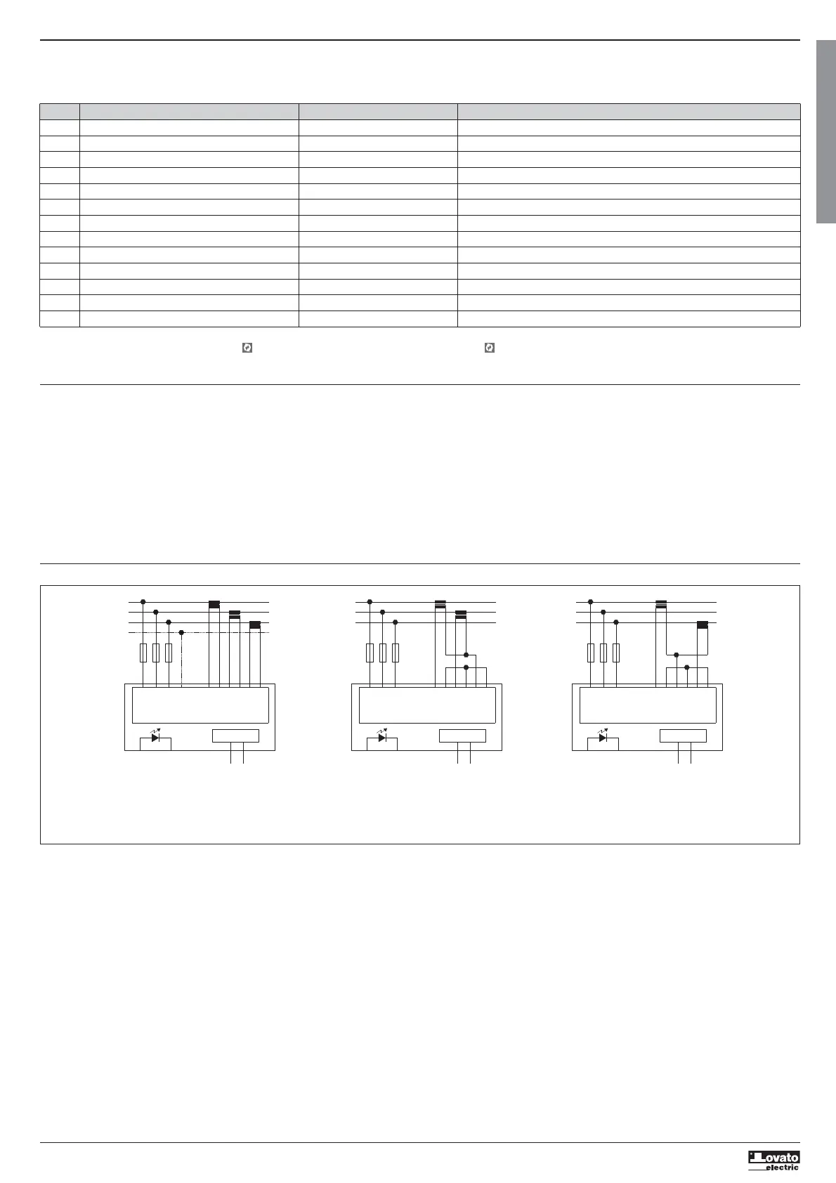
WIRING DIAGRAM
L1
L3
L2
N
VN
S2
I2
T2T1
METER
V2
V1
V3
S1
I1
S2
S1
I3
S2
S1
100...240V~
Tariff input
L1
L3
L2
S2
I2
T2T1
METER
V2
V1
V3
S1
I1
S2
S1
I3
S2
S1
M-BUS
M1
M2
100...240V~
Tariff input
L1
L3
L2
S2
I2
T2T1
METER
V2
V1
V3
S1
I1
S2
S1
I3
S2
S1
100...240V~
Tariff input
S1
S2
S1
S2
S1
S2
S1
S2
M-BUS
M1
M2
M-BUS
M1
M2
NOTES
1. Recommended fuses: F1A (fast).
2. The S2 terminals are connected to each other internally.
 Loading...