I511 GB I 09 17 31100346
G
B
9
– The following table lists the available menus:
CODE MENU DESCRIPTION
P01 GENERAL Specifications of the system
P02 UTILITY Language, brightness, display, etc.
P03 PASSWORD Enablement of protected access
P04 INTEGRATION Readings integration times
P05 HOUR COUNTER Enablement of hour counter
P07 COMMUNICATION Communication port
P08 LIMIT THRESHOLDS (LIMn) Measurement thresholds
P09 ALARMS (ALAn) Alarm messages
P13 INPUTS Programmable input
– Press to access the selected menu.
– At this point the sub-menu (if applicable) and sequential parameter number can be selected, again using the buttons as follows:
•
and
simultaneously: back
•
decrease
•
increase
• next
– Once the desired parameter number is set, switches to parameter value edit mode, with the parameter shown in the alphanumeric display.
– Pressing
or
changes the parameter within the permitted range.
– Pressing
and simultaneously sets the minimum possible value, while pressing
and sets the maximum.
– Pressing
and
simultaneously restores the factory default value.
– After selecting the desired value, pressing stores the parameter and returns to the previous level, i.e. parameter selection.
– Press
and
simultaneously several times to exit and save the parameters. The device will reboot.
– If no buttons are pressed for two minutes, the setup menu is abandoned automatically and the system returns to the standard display without saving the parameters.
– Remember that, solely for the data that can be edited using the buttons, a backup copy can be made in the DME D332’s EEPROM. If required, this data can be restored to the working memory. The backup and data
restore commands are in the commands menu.
PARAMETER TABLE
– All available programming parameters are indicated in the following table. For each parameter the range of possible settings and factory default are shown, in addition to an explanation of the parameter’s function.
The description of the parameter visible on the display may in some cases vary from that indicated in the table due to the limited number of characters available. The parameter code is a valid reference in any case.
M01 - GENERAL UoM Default Range
P01.01 CT primary A 5 1-10000
P01.02 CT secondary A 5 1-5
P01.03 Nominal voltage V AUT AUT / 220-415
P01.04 Nominal power kW AUT AUT / 1-10000
P01.05 Connection type L1-L2-L3-N L1-L2-L3-N
L1-L2-L3
L1-L2-L3-N BIL
L1-L2-L3 BIL
L1-N-L2
L1-N
P01.01 – Rated current of CT primary winding.
P01.02 – Current of CT secondary winding.
P01.03 – Rated voltage of system.
P01.04 – Rated power of system.
P01.05 – Set in accordance with the connection scheme adopted. See Wiring Diagram at the end of the manual.
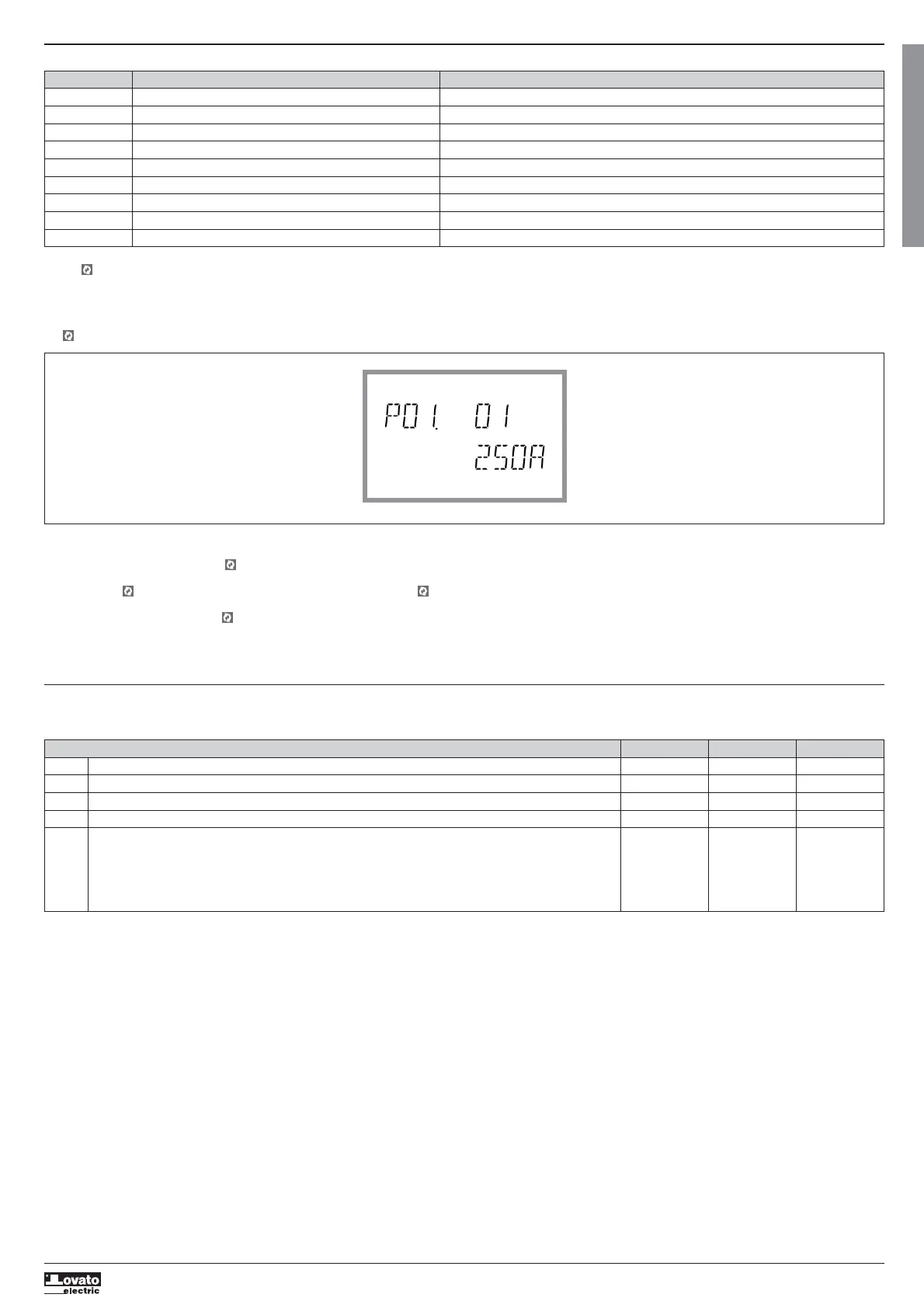
Setup: selecting the parameter number
 Loading...