I451 I GB D F E 10 16 4257Z010
I
14
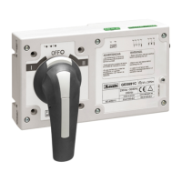
2 - Inserire l'albero di collegamento e fissarlo con una chiave a brugola da 2,5 DIN 90011. Senza togliere il coperchio anteriore, togliere le quattro viti indicate.
3 - Posizionare l'interfaccia ed avvitarla sul commutatore usando viti M3.5x30 DIN7985 (q.tà 4) e rondelle AET 4,3 (q.tà 4) già incluse nel kit.
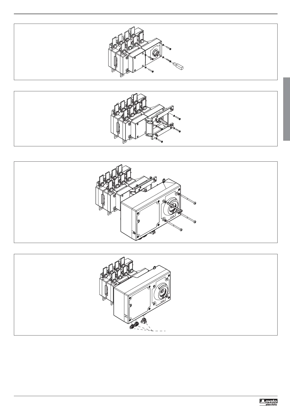
4 - Avvitare l'unità motorizzata [con commutatore e unità motore in posizione 0 (OFF)]. Le viti M5 x 75 DIN 7985 (q.tà 4), le rondelle AET 5,3 (q.tà 4) e i dadi M5 DIN 933 (q.tà 4) sono compresi nel
kit.
5 - Montare i connettori (CN1, CN2, CN3) ed effettuare i collegamenti sulla base dello schema elettrico (vedere allegato 3, pagina 19).
CN1, CN2, CN3
 Loading...