4 -20
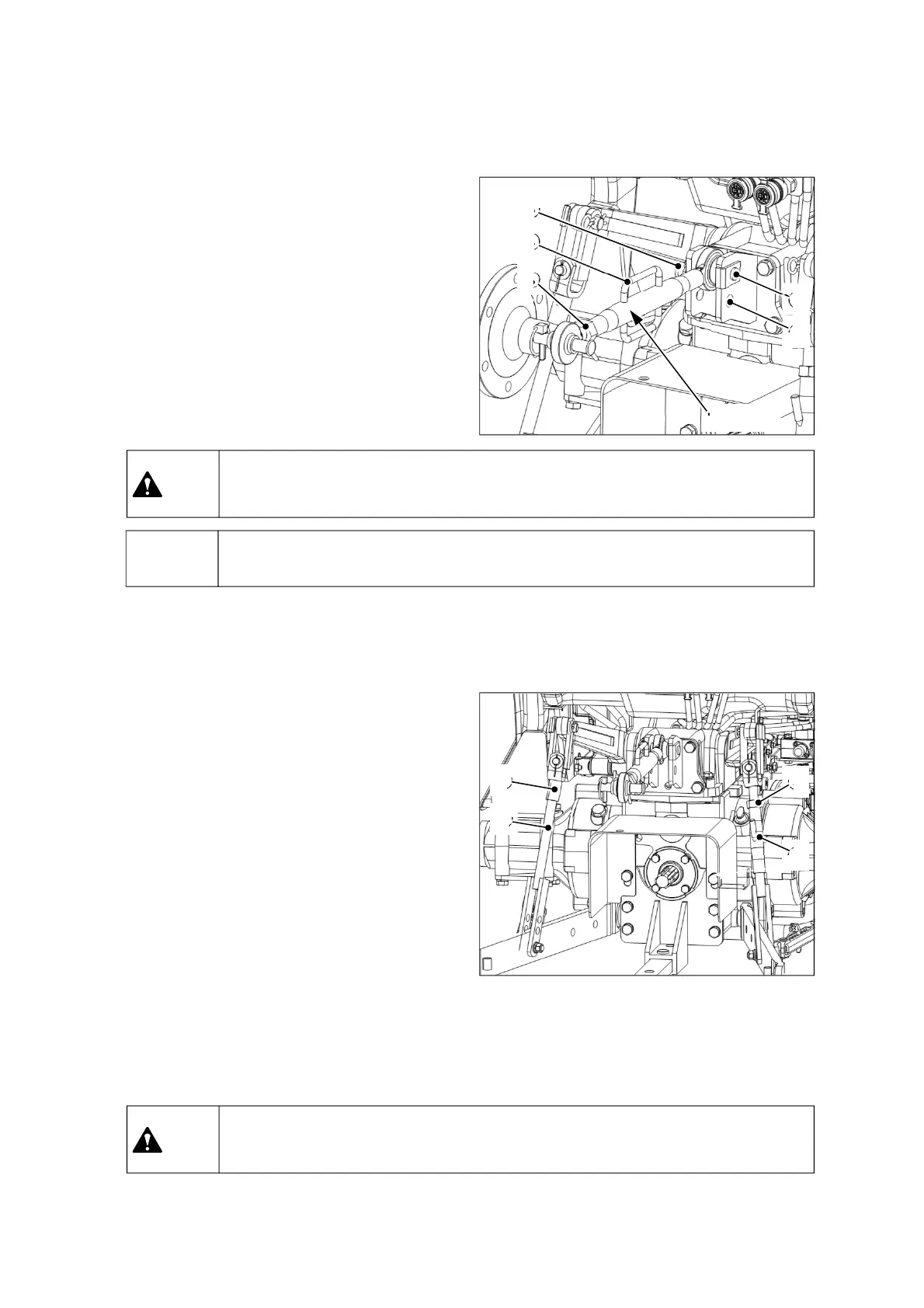
① Upper link installation and
adjustment
Select a suitable attaching hole(2) on the top link
bracket depending on the implement.
Adjust the length of the upper link by turning the
handle(4) after releasing the locking nut (3).
Fasten the locking nut (3) after adjusting the
length.
Adjustment range: 430~654mm (16.9~25.7 in)
▶ Insert the snap-pin(6) firmly to prevent the upper link pin(5) from being escaped.
Notice
② Adjustment of lift-rod (Left/Right)
For lift rod (LH), detach the upper side from the
lift arm and adjust the length by turning the
upper side(1).
-Adjustment range: 492~502mm (19.4~19.8 in)
For lift rod (RH), turn the handle(4) to the right to
shorten the rod. If turning it to the left, the rod is
elongated. After adjustment, tighten the locking
nut(3).
-Adjustment range: 445~538mm (17.5~21.2 in)
If assembling the lower link to the upper hole of
the lift rod, it can additionally shorten the length
by 63mm(2.5 in).
⑥
④
②
⑤
③
④
③
①
②
Upper link
▶ Do not adjust the length of the upper link over the maximum limit. It may cause
fatal injury or death by falling object.
Caution
▶ Do not adjust the length of the lift-rod over the maximum limit. It may cause fatal
injury or death by falling object.
Caution