4 -19
▶When adjusting the stabilizer’s length, set the lateral swinging clearance of the
implement to be 20~40mm. (0.8~1.6 in.)
Notice
③ Adjustment of stabilizer (optional)
- Check link type
Pull up the link pin(1) and turn the grip of the
stabilizer clockwise/counter-clockwise.
Insert the link pin(1) into the hole and let it
tightened firmly by locking spring.
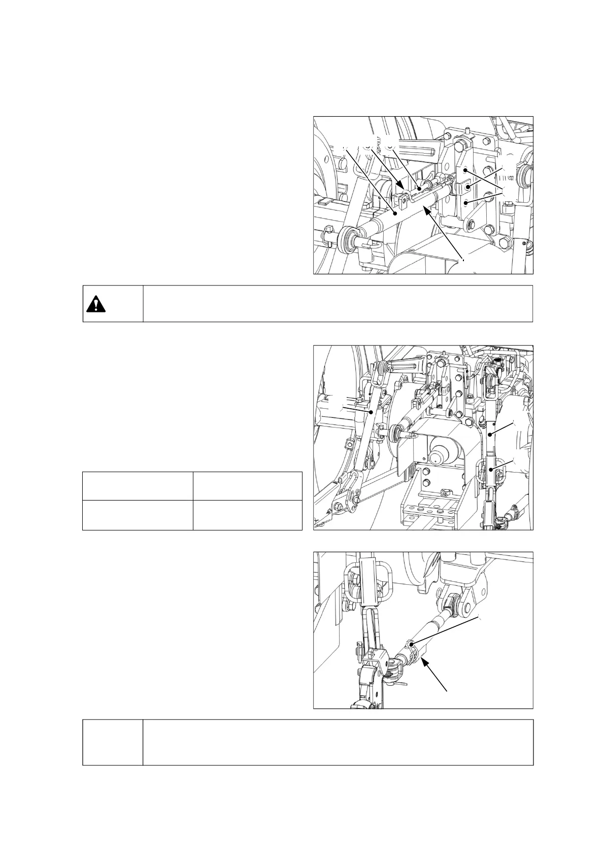
Lift rod(LH) Lift rod(RH)
510~545~580 mm
(20.1~21.5~22.8 in)
492~592 mm
(19.4 ~ 23.3in)
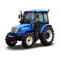
① Upper link installation and
adjustment
Select a suitable attaching hole(2) depending on
the implement. The upper hole is more sensible
than lower one for draft load control.
To adjust the length of the upper link, release the
locking spring(3) and turn the sleeve(4) with
handle(6).
Fix the handle(6) with locking spring(3) after
adjusting.
Adjustment range: 520~780mm (20.5~30.7 in)
▶ Do not adjust the length of the upper link and lift-rod over the maximum limit. It
may cause fatal injury or death by falling object.
② Adjustment of lift-rod (Left/Right)
For lift rod (LH), detach the lower side of the lift-
rod(LH) from the lower link and reassemble it to
the other hole.
For lift rod (RH), lift up the handle(4) and turn it
to the left or right to adjust the length Lock the
handle(4) in place after adjusting.
⑥
④
②
⑤
③
Upper link
④
③
①
①
Stabilizer
Caution