Industrial Drive for Fan and Pump STARVERT iP5A
Jumper
Jumper
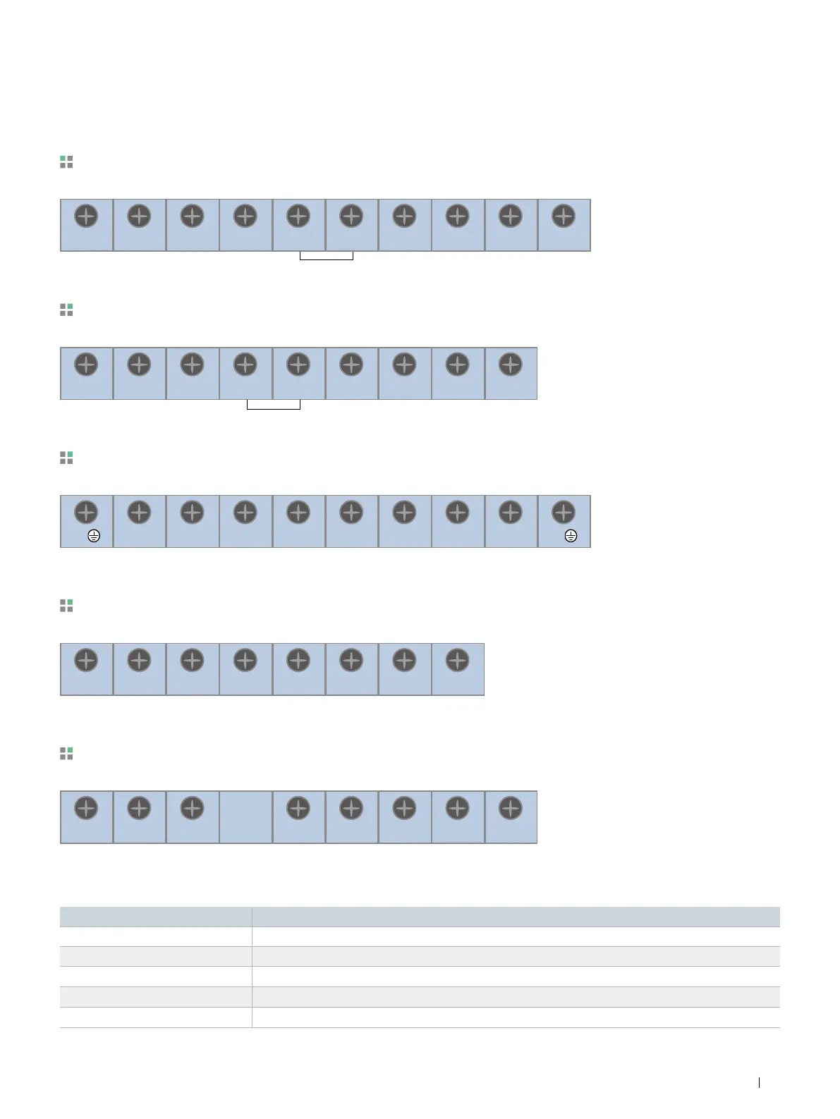
Terminal Configurations (Power Circuit Terminal)
Symbol
Description
R, S, T (L1, L2, L3) AC Line Voltage Input
G Earth Ground
P1 (+), P2 (+) External DC Reactor [P1 (+)-P2 (+)] Connection Terminals (Jumper must be removed).
P2 (+), N (-) or P (+), N (-) DB Unit [P2 (+)-N (-)] Connection Terminals
U, V, W 3 Phase Power Output Terminals to Motor
0.75~30kW (1~40HP) <200V/400V/600V Class>
37~90kW (50~125HP) / 315~450kW (400~600HP) <400V/600V Class>
R
(
L1
)
(+) (+) (--)
(+) (+) (--)
S
(
L2
)
T
(
L3
)
G P1 P2 N U V W
R
(
L1
)
S
(
L2
)
T
(
L3
)
P1 P2 N U V W
15~18.5kW (20~25HP) <Built-in DC Reactor Type, 400V Class>
(+) (--)
R
(
L1
)
G S
(
L2
)
T
(
L3
)
P N U V W G
22~30kW (30~40HP) <Built-in DC Reactor Type, 400V Class>
(+) (-)
R
(
L1
)
S
(
L2
)
T
(
L3
)
P N U V W
37~90kW (50~125HP) / 110 ~280kW (150~350HP) <Built-in DC Reactor Type, 400V Class>
(+) (--)
R
(
L1
)
S
(
L2
)
T
(
L3
)
P2 N U V W
Note) P1 (+) is not provided for wiring.
17
Drive Starvert iP5A Series