Power
PE
Supply
Noise
Filter
PLC
Input/Output
PLC Power
Programmable Logic Controller Installation Guide
XB(E)C-DR32/64H(/DC)
XB(E)C-DN32/64H(/DC)
This installation guide provides simple function information of PLC control. Please read carefully
this data sheet and manuals before using products. Especially read safety precautions and
handle the products properly.
■ Meaning of warning and caution inscription
WARNING indicates a potentially hazardous situation which,
if not avoided, could result in death or serious injury
CAUTION indicates a potentially hazardous situation which,
if not avoided, may result in minor or moderate injury.
It may also be used to alert against unsafe practices
①
Do not contact the terminals while the power is applied.
② Protect the product from being gone into by foreign metallic matter.
③ Do not manipulate the battery(charge, disassemble, hitting, short, soldering)
① Be sure to check the rated voltage and terminal arrangement before wiring
② When wiring,tighten the screw of terminal block with the specified torque range
③ Do not install the flammable things on surroundings
④ Do not use the PLC in the environment of direct vibration
⑤ Except expert service staff, Do not disassemble or fix or modify the product
⑥ Use the PLC in an environment that meets the general specifications contained
in this datasheet.
⑦ Be sure that external load does not exceed the rating of output product.
⑧ When disposing of PLC and battery, treat it as industrial waste.
To install, observe the below conditions.
℃
℃
5 ~ 95%RH, non-condensing
5 ~ 95%RH, non-condensing
5
Vibration
Resistance
Frequency Acceleration Amplitude Times
IEC 61131-2
each
direction
for
X, Y, Z
This is Performance specification of XGB. For more details, refer to related manual.
Operation method
Reiterative operation, fixed cycle operation,
Interrupt operation, constant period scan
I/O control method
Scan synchronous batch processing (refresh method)
Direct method by instruction
Basic instruction: 60ns/step
XBC:15Kstep, XEC: 250KB
Main +
Expansion
10 Slot(expansion slot)
Delay of operation, abnormal memory, abnormal I/O
Data keeping method at
power failure
Setting latch(retain) area at basic parameter
Cnet(RS-232C,RS-485), PID, High speed counter, RTC
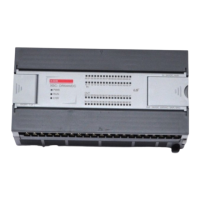
Parts name and Dimension (mm)
■ This is front part of the CPU. Refer to each name when driving the system. For more
information, refer to user manual.
① Built-in Communication Terminal block
③ 24V Output(Sub-power, Not applied to /DC power unit)
④ PADT Connect(USB, RS232)
■ Dimension(mm)
Applicable Support Software
■ For system configuration, the following version is necessary.
1) XG5000 Software : V4.71 or above
2) XBO-M2MB : V1.60 or above
Accessories and Cable Specifications
■ Check the accessory. (Order the cable if need)
1) PMC-310S : RS-232 connecting (download) cable.
2) USB-301A : USB connecting(download) cable.
Installing / Removing Modules
■ Here describes the method to installing removing product.
1) Installing module
① Eliminate the Extension Cover at
the product.
② Push the product and connect it in
agreement with Hook For Fixation
of four edges and Hook For
Connection at the bottom.
③ After connection, push down the
Hook For Fixation and fix it
completely.
2) Removing module
① Push up the Hook For removing, and then installing the product with two hands.
(Do not remove the product by force)
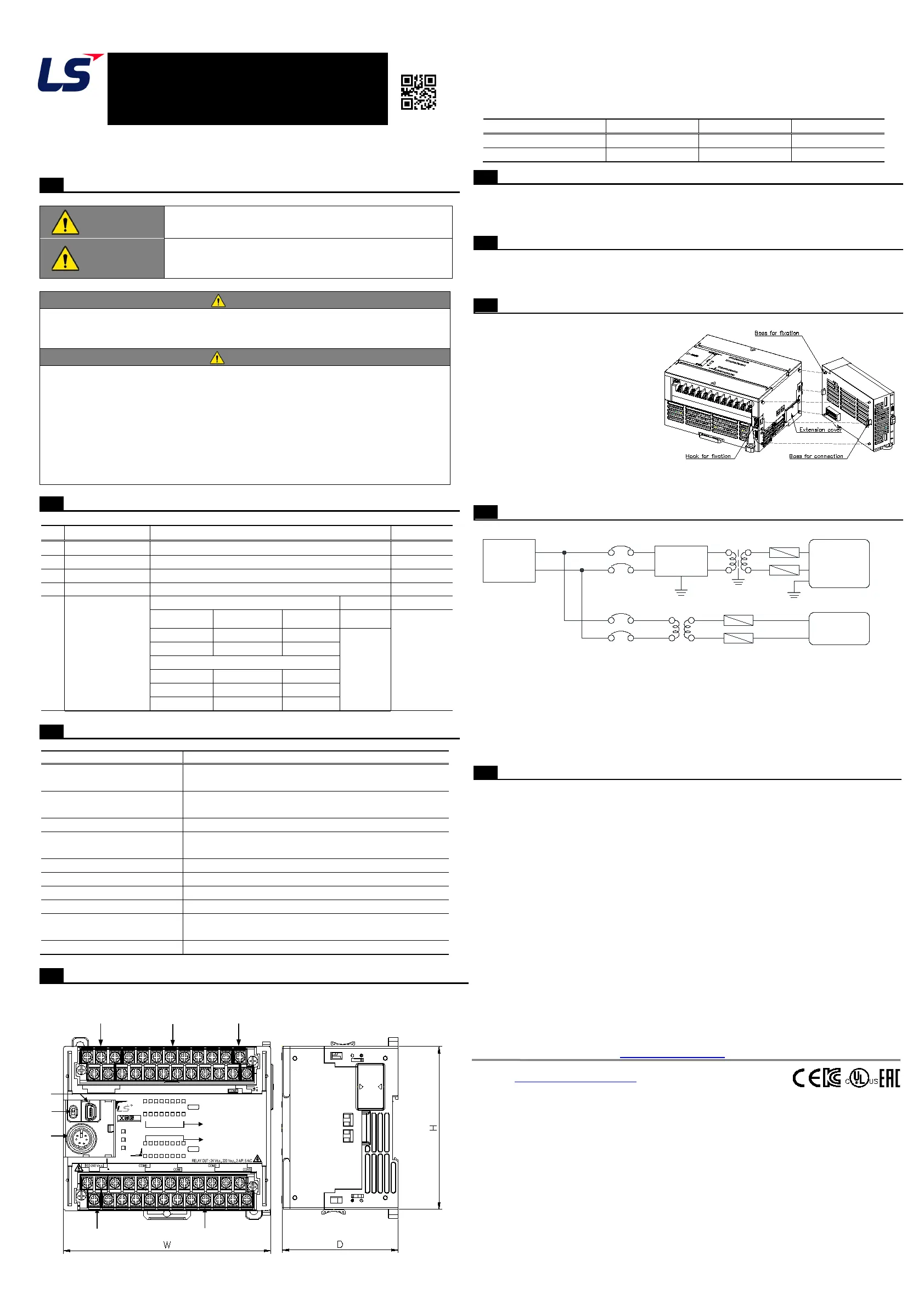
■ Power wiring
.
1) In case that the power change is larger than the range of standard, connect
constant voltage transformer
2) Connect the power having the small noise between cables or between earths.
In case of having lots of noise, connect the isolating transformer or noise filter.
3) power for PLC, I/O device and other machines should be separate.
4) Use the dedicated earth if possible. In case of Earth works, use 3 class earth
(earth resistance 100 Ω or less) and Use more than 2 mm2 cable for earth.
If the abnormal operation is found according to the earth, separate the earth
■ The warranty period is 36 months from the date of manufacture.
■ The initial diagnosis of faults should be conducted by the user. However, upon request, LS
ELECTRIC or its representative(s) can undertake this task for a fee. If the cause of the fault
is found to be the responsibility of LS ELECTRIC, this service will be free of charge.
■ Exclusions from warranty
1) Replacement of consumable and life-limited parts (e.g. relays, fuses, capacitors, batteries,
LCDs, etc.)
2) Failures or damages caused by improper conditions or handling outside those specified in
the user manual
3) Failures caused by external factors unrelated to the product
4) Failures caused by modifications without LS ELECTRIC’s consent
5) Use of the product in unintended ways
6) Failures that cannot be predicted/solved by current scientific technology at the time of
manufacture
7) Failures due to external factors such as fire, abnormal voltage, or natural disasters
8) Other cases for which LS ELECTRIC is not responsible
■ For detailed warranty information, please refer to the user’s manual.
■ The content of the installation guide is subject to change without notice for product
performance improvement.
LS ELECTRIC Co., Ltd. www.ls-electric.com 10310001847 V1.1 (2024.06)
• E-mail: automation@ls-electric.com
• Headquarter/Seoul Office
Tel: 82-2-2034-4033,4888,4703
• LS ELECTRIC Shanghai Office (China)
• LS ELECTRIC (Wuxi) Co., Ltd. (Wuxi, China)
• LS-ELECTRIC Vietnam Co., Ltd. (Hanoi, Vietnam)
• LS ELECTRIC Middle East FZE (Dubai, U.A.E.)
• LS ELECTRIC Europe B.V. (Hoofddorf, Netherlands)
• LS ELECTRIC Japan Co., Ltd. (Tokyo, Japan)
• LS ELECTRIC America Inc. (Chicago, USA)
• Factory: 56, Samseong 4-gil, Mokcheon-eup, Dongnam-gu, Cheonan-si, Chungcheongnam-
do, 31226, Korea
Performance specifications
00
20
01
21
02
22
03
23
04
24
05
25
06
26
07
27
08 09 0A0B0C0D0E 0F
RUN
PWR
ERR
DC IN : 24 Vd.c., 4 mA
0.4A
130 VA 50/60 Hz
P0C P0E
P01 P03 P05 P07 P09 P0B P0D P0F
P0AP08P06P04P02P00
P24 P26
P29 P2B P2C P2E
P25 P27 P28 P2A
P2D P2F
SGTXRX
485-485+
24V
24G
P21 P23
P22P20
PE
L N
28
29 2A 2B 2C2D 2E 2F
XBC- DR32H
IN
OUT
1847
 Loading...