THE GS320 SYSTEM
4: INSTALLATION
4.1 Display GS320
INSTALLATION MUST BE MADE IN
COMPLIANCE WITH LSI-ROBWAY
INSTRUCTIONS AND USING LSI-ROBWAY
SUPPLIED COMPONENTS ONLY.
faIlURe To InsTall all PaRTs, oR
RePlaCIng PaRTs oR CoMPonenTs WITH
PaRTs oR CoMPonenTs noT sUPPlIeD
bY LSI-ROBWAY, MaY leaD To sYsTeM
faIlURe, seRIoUs InJURY, oR DeaTH.
WARNING
DO NOT CRACK OR PUNCTURE THE FACE
COVER MEMBRANE.
DO NOT POWER WASH THE DISPLAY.
THe gs550 UnDeRHooK DIsPlaY
Is sPlasH- anD RaIn-PRoof.
WaTeRPRoofIng DePenDs In PaRT on
THe InTegRITY of THe MeMbRane. PoWeR
WasHIng WIll VoID THe WaRRanTY.
CAUTION
6.19
4.70
1.37
Adjustable
Ram-Bracket
with dual ball joints.
Part number: LB002B
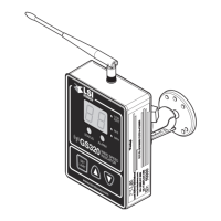
Rugged
aluminium
enclosure
Two way radio
system
Waterproof
design
Field replaceable
antenna
Part number: TA008
2.20
6.49
3.70
8.83
2.44
Figure 10: Display dimensions (inches). Not to scale
4.1a Mounting Bracket
1. Determine the mounting location; the display may be
installed either inside or outside the cab. It can be
mounted on the dash, on a sidewall, or on the ceiling
of the cab.
To ensure reliable radio communication between wind
speed sensor and the GS320, the antenna should
not be in contact with metal and should have a direct
and clear line of sight to the sensor antenna. The
mounting bracket requires a flat surface of at least 2.5
inches in diameter on both sides and where the back
of the surface is accessible in order to tighten the nuts.
F
igure 11:
Display mounting bracket footprint. Not to scale
0.906
ø0.218
flat surface
120° TYP
0.594
0.594
2. Drill 1/4-inch boltholes through the mounting surface
with a 1/4-inch bit following either the two-, three-, or
the four-hole configuration.
3. Install the display with bolts. Add washers and
lock nut behind the mounting surface and tighten
sufficiently (bolts, nuts and washers not included).
If THe nUTs aRe on THe oUTsIDe of THe
Cab, CaUlK WITH sIlICone beTWeen
THe WasHeRs anD THe Cab To PReVenT
WaTeR enTRY.
NOTE
✓
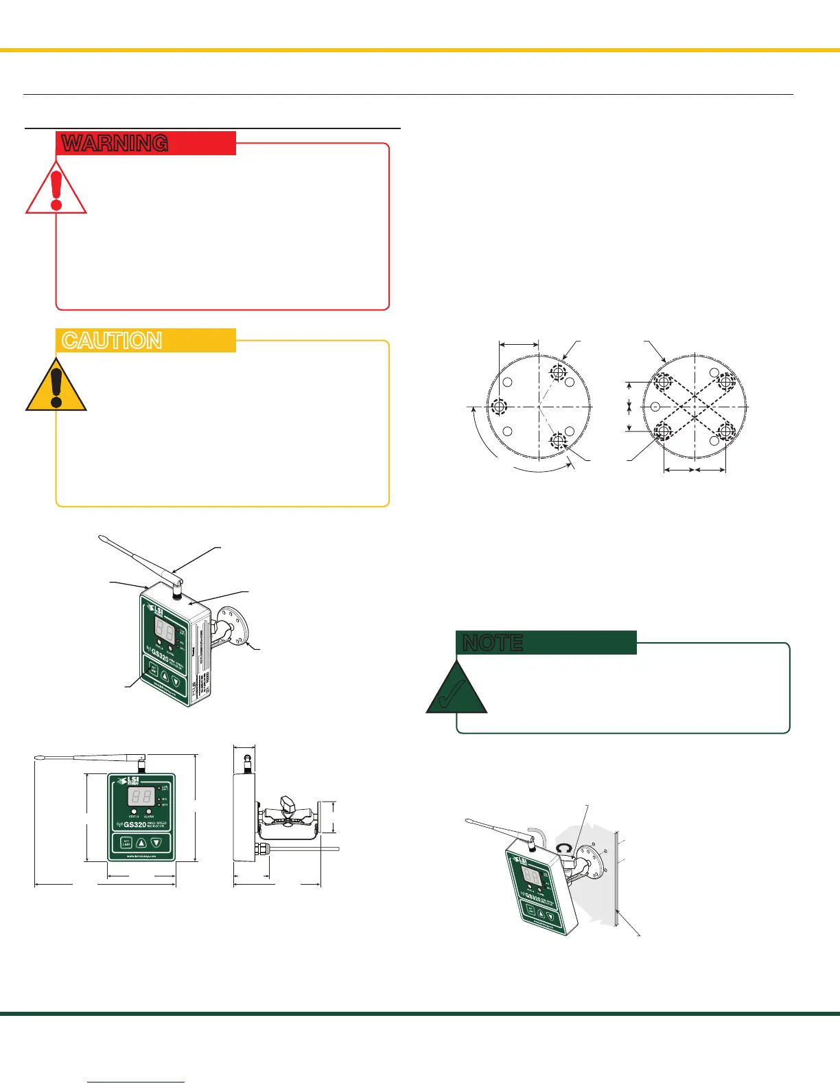
4. Loosen the wing nut of the bracket arm to adjust
display orientation to facilitate viewing by the operator
and then tighten it back up.
Cab mounting
surface
Wing
Nut
Figure 12: Install the display and adjust orientation
SkyAzúl, Equipment Solutions