THE GS320 SYSTEM
4.1b Antenna Position
For optimal performance, the antenna should be
positioned on its side such that it is parallel to the
sensor antenna (but not pointing directly to or directly
away from it).
5. Adjust the antenna position with the articulating base.
6. The antenna should have 5 inches of clear space all
around it.
7. The antenna should have an unobstructed line of sight
to all sensor antennas at all boom angles.
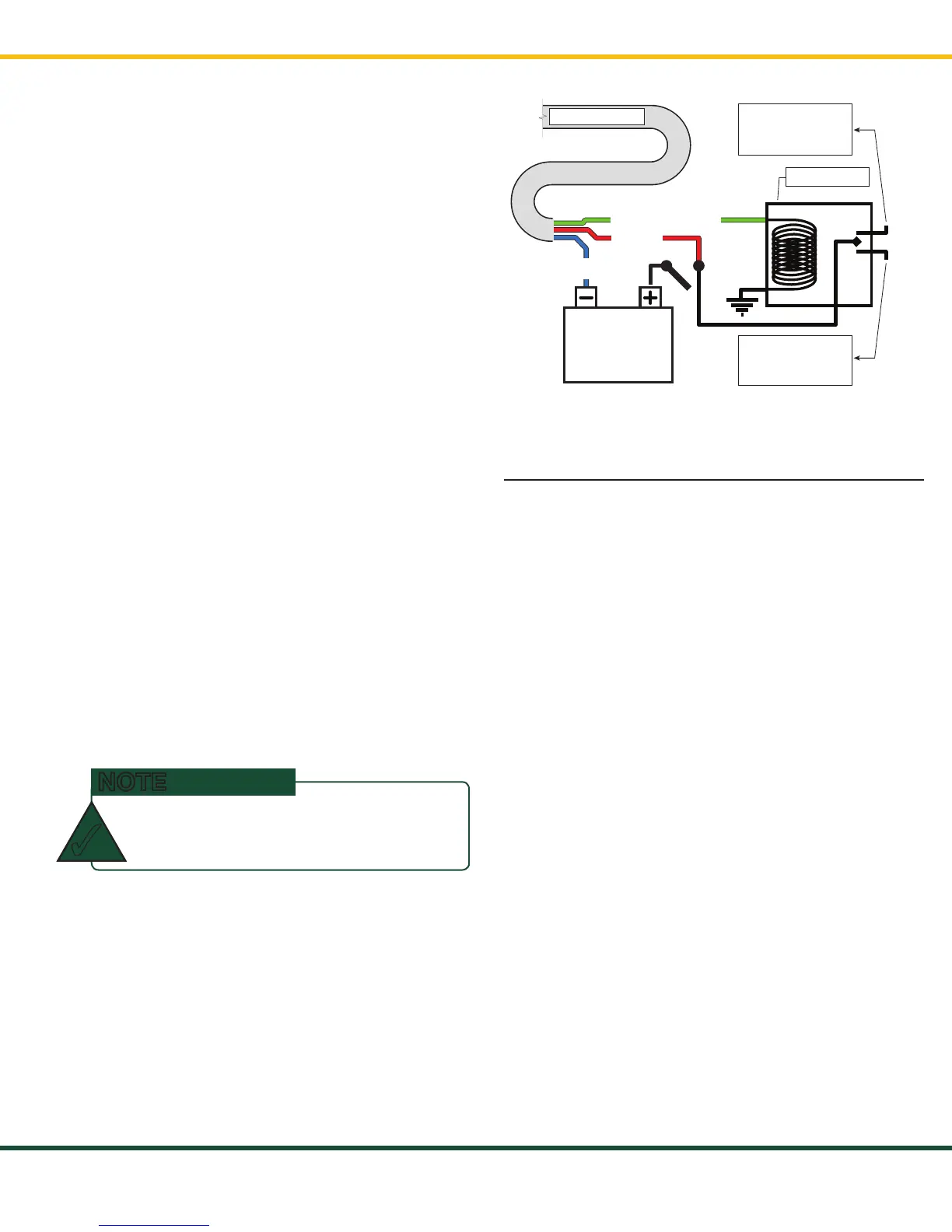
4.1c Power Supply and Lockout Connection
1. Connect the blue wire (ground) to the negative
terminal of the battery or the panel connection;
alternatively, bolt the blue wire to the body of the
machine with a 1/4-inch or 5/16-inch bolt. The
ground connection must be strong enough to sustain
three amperes.
2. Connect the red wire to a fused accessory source,
rated at least three amperes, that supplies +12 or
+24 volts when the machine is in use. The GS320 will
automatically detect the voltage level and adjust itself.
3. Lockout wire (if required): connect the green wire to
a Bosch relay coil terminal. Connect the other coil
terminal of the relay to the ground. When in safe
condition, the green wire will energize at the battery
positive level.
4. Any current greater than one ampere on the green
wire triggers an auto re-settable fuse. Current will
resume flowing several seconds after the short circuit
is eliminated.
If no VolTage Is PResenT on THe gReen
WIRe, ReMoVe THe loaD ConneCTeD To IT.
NOTE
✓
n.c.
n.o.
co
Power Supply
or Battery
+12 V or +24 V
Blue
wire
Red wire
Green wire - Lockout
To valve coil if
normally open is
required
← To GS320
To valve coil if
normally closed
is required
Bosch relay
Figure 13: Connection with green wire lockout and
recommended Bosch relay
4.2 Power Supply Verification
The power from the crane needs to be checked in the
DC and AC modes under the following conditions:
• Engine start-up
• Engine idling
• Engine revving up, during complete process (not
just when it is revved up)
• Engine revving down (same process as above)
• Engine shut-down
The DC power should not exceed 30 VDC and the AC
should be negligible (e.g. <1 VAC).
SkyAzúl, Equipment Solutions