ISTALLATIO
ISTALLATIO
5
5
2.1
2.1
Display GS375
Display GS375
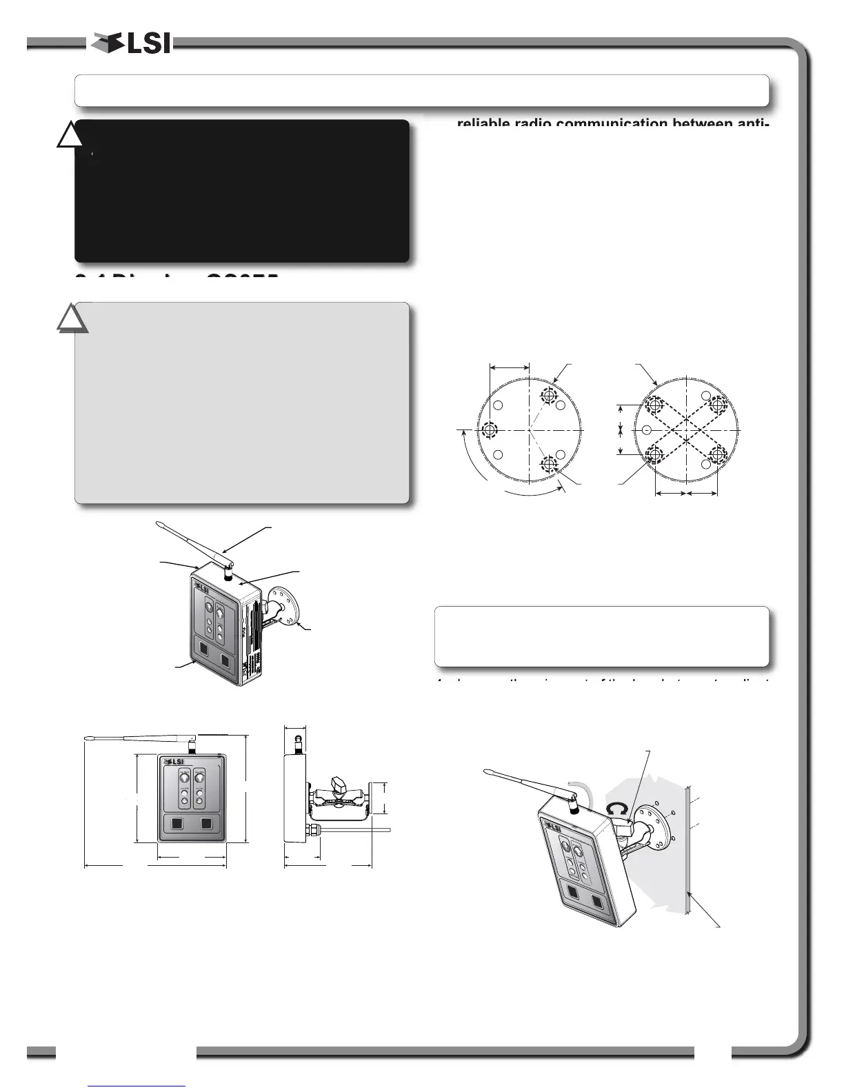
2.1a Mounting Bracket
1. Determine the mounting location; the display
may be installed either inside or outside the
cab. It can be mounted on the dash, on a
sidewall, or on the ceiling of the cab. To ensure
reliable radio communication between anti-
two-block switch and the GS375, the
antenna should not be in contact with metal
and should have a direct and clear line of
sight to the sensor antenna. The mounting
bracket requires a flat surface of at least 2.5
inches in diameter on both sides and where the
back of the surface is accessible in order to
tighten the nuts.
2. Drill 1/4 inch boltholes through the mounting
surface with a 1/4 inch bit following either the
two, three, or the four holes configuration.
3. Install the display with bolts. Add washers and lock
nut behind the mounting surface and tighten
sufficiently (bolts, nuts and washers not included).
4. Loosen the wing nut of the bracket arm to adjust
display orientation to facilitate viewing by the
operator and then tighten it back up.
2.
2.
INSTALLATION
INSTALLATION
with dual ball joints.
ø2.5 in. min.
IMPORTANT!
Do not crack or puncture
the membrane fascia. The GS375 display is
splash and rain proof. Waterproofing depends in
part on the integrity of the membrane.
IMPORTANT!
Do not power wash the
display. The GS375 display is not designed to
withstand high-pressure washing devices that
can erode the membrane fascia seal or create
fissures in the membrane fascia. Power washing
the display voids warranty coverage.
!
!
Note: If the nuts are on the outside of the cab,
caulk with silicone between the washers and the
cab to prevent water entry.
WARNING!
Installation must be made in
compliance with
LSI
LSI instructions and using
supplied components only. Failure to install
all parts, or replacing parts or components
with parts or components not supplied by
LSI
LSI, may lead to system failure, serious
injury or death.
!
!