6
6
The GS375 System
The GS375 System
2.1b Antenna Position
For optimal performance the antenna should be
positioned on its side such that it is parallel to
the sensor antenna (but not pointing directly to or
directly away from it).
1. Adjust the antenna position with the articulating base.
2. The antenna should have 5 inches of clear
space all around it.
3. The antenna should have an unobstructed line of
sight to all sensor antennas at all boom angles.
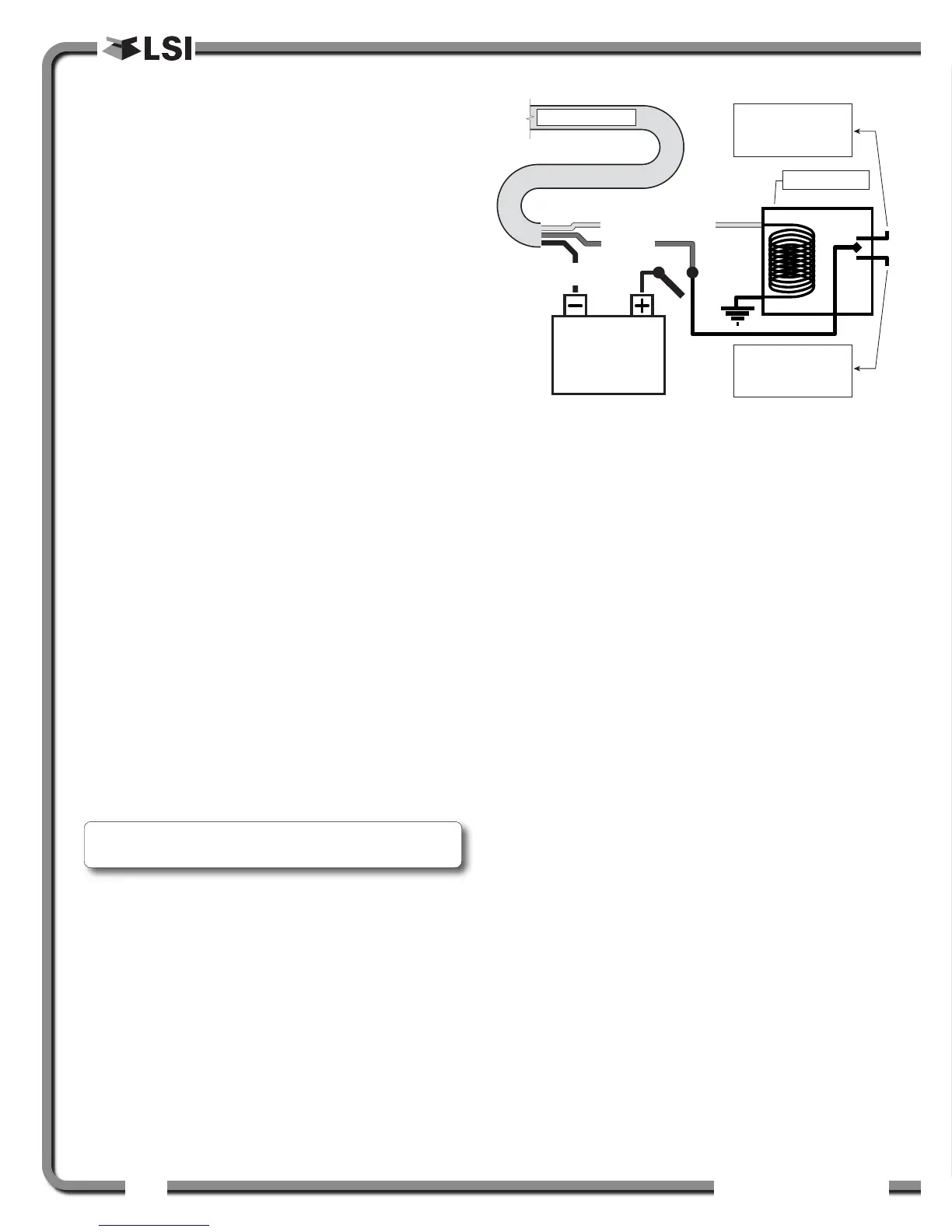
2.1c Power Supply and Lockout
Connection
1. Connect the blue wire (ground) to the negative
terminal of the battery or the panel connection;
alternatively bolt the blue wire to the body of the
machine with a 1/4 inch or 5/16 inch bolt. The
ground connection must be strong enough to
sustain 3 amperes.
2. Connect the red wire to a fused accessory
source, rated at least 3 amperes, that supplies
+12 or +24 volts when the machine is in use.
The GS375 will automatically detect the voltage
level and adjust itself.
3. Lockout wire (if required): connect the green
wire to a Bosch relay coil terminal. Connect the
other coil terminal of the relay to the ground.
When in alarm, the green wire will energize at
the battery positive level.
Current over 1 ampere on the green wire
triggers an auto re-settable fuse. Current flow
will resume several seconds after the short
circuit is eliminated.
n.c.
n.o.