ISTALLATIO
ISTALLATIO
7
7
2.2
2.2
GS050 Anti-Two block
GS050 Anti-Two block
Switch and
Switch and
GS075 All-In-One Anti-Two-
GS075 All-In-One Anti-Two-
Block Switch and Weight
Block Switch and Weight
Verify the anti-two-block switch is programmed to
the GS375 display. Switches shipped with displays
are pre-programmed in the factory. Test
: if the
switch has been programmed to the display then
the display will go in to two-block alarm when the
wire rope of the switch is released. Press Bypass
to silence the alarm until the next two-block event
or simulation. If the switch has not been
programmed to the display, this should be done
before proceeding with installation. See the section
3.1 Set the ID Number.
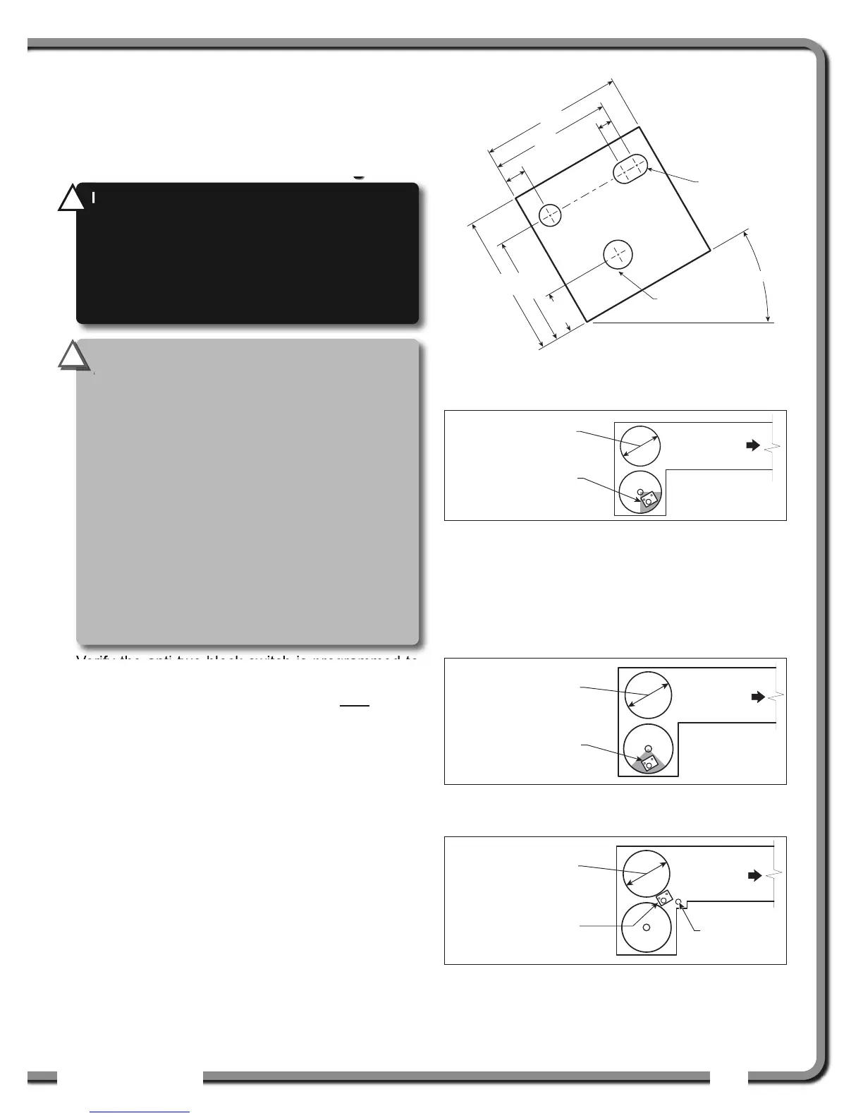
2.2a GS050 Installation
1. Position the sensor mounting bracket. To
ensure that the sensor can pivot securely on the
mounting bracket throughout the full range of
boom angle, the mounting bracket must be
positioned at a 30° from horizontal with the
boom parallel to the ground and such that the
locking pin of the mounting bracket points up.
Bolt or weld securely.
If the head sheave diameter is between 8 and 16
inches (20-41 centimetres) then two mounting
brackets will be required to permit both live and dead
end mounting.
ø0.38
Pivot Center
(Anchor shaft)
30°
2.50
2.125
0.375
0.25
2.5
1.9375
0.75
Up to 8 in. (20 cm)
diameter
Boom
base
Mount bracket below
and behind sheave
center.
Figure: Anti-two-block switch placement on a telescopic boom
Figure: Bracket footprint and orientation,
All dimensions are in inches. Not to scale.
8-16 in. (20-41 cm)
diameter
Boom
base
Mount bracket 4 in.
(10 cm) below sheave
center.
Figure: Anti-two-block switch placement for live end mounting
on a lattice boom
8-16 in. (20-41 cm)
diameter
Boom
base
Dead
end pin
Mount bracket 4 in.
(10 cm) in front of the
dead end pin.
Figure: Anti-two-block switch placement for dead end
mounting on a lattice boom
WARNING!
Keep the anti-two-block switch
away from the boom and any connecting
metal structures when welding mounting
brackets to the boom. Proximity to welding
may cause permanent damage to the anti-
two-block switch and render the anti-two-
block system unsafe.
!
!
IMPORTANT!
To ensure reliable radio
communication between the anti-two-block
switch and the GS375 display the following
conditions must be respected:
• The antenna of the anti-two-block switch
should not be in contact with metal.
• The anti-two-block switch antenna should
point to the left or to the right of the boom;
it should not point directly to, or away from,
the GS375 display.
• The anti-two-block switch antenna should
have a clear line of sight to the GS375
display; in most cases this means mounting
the sensor on the same side of the boom as
the operator's cab.
!
!