8
8
The GS375 System
The GS375 System
For live end mounting on multiple sheave blocks
with sheaves greater than 16 inches (41
centimetres) in diameter consult your service
representative.
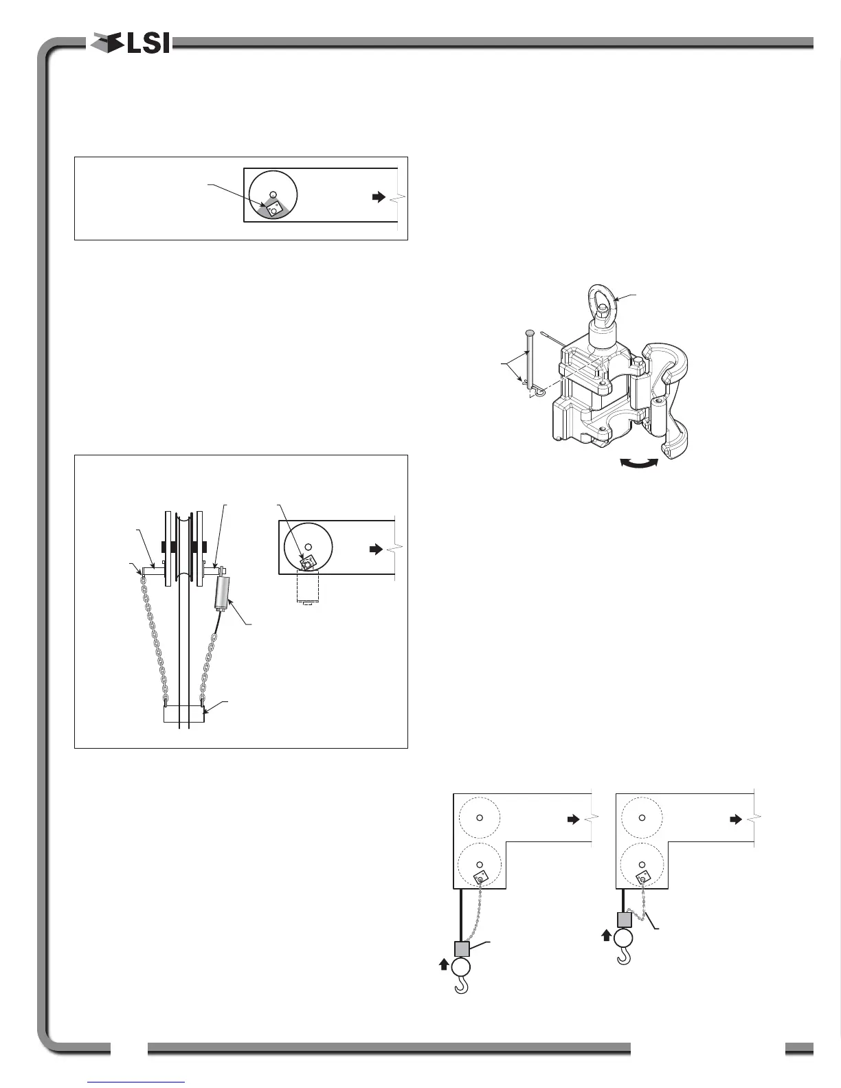
For fast line weight installation place the anti-two-
block switch mounting bracket directly below the
sheave center as low and as close to the edge of
the sheave as possible. Place the fast line weight
mounting bracket on the opposite side of the
sheave with the chain hole pointing down and lined
up opposite the pivot of the anti-two-block switch
mounting bracket.
2. Mount the GS050 on the bracket and verify that
the GS050 can rotate freely through all possible
boom movements without being able to come
off the bracket.
3. Install the weight and chain assembly around
the cable and attach the other end of the chain
to the GS050. Tighten all the chain links of the
chain assembly.
4. Adjust chain length as required, see sub-section
Chain length adjustment.
5. Test system function.
2.2b GS075 Installation
1. Optional Bracket: Position the optional mounting
bracket on the boom. Bolt or weld securely.
2. Attach one end of the chain assembly to the
optional bracket or to the boom and the other
end to the eye bolt of the GS075. Tighten all the
chain links of the chain assembly.
3. Remove the hair pin and the clevis pin and
open the back end of the GS075. Install the
GS075 around the cable and then put the clevis
pins (2) back in.
4. Adjust chain length as required, see sub-section
Chain length adjustment.
5. Test system function.
2.2c Chain length adjustment
1. Chain length adjustment № 1 – minimum boom
angle
a. At minimum boom angle, with no
additional weight on the hook block and
one part of line only, lift the boom just
enough to have the hook block suspend
and clear the sensor chain and weight.
b. Hoist slowly until the buzzer sounds. Note
Mount bracket 4 in.
possible.