Do you have a question about the LSIS GIPAM 115 FI and is the answer not in the manual?
Explains the meaning of warning symbols used in the manual.
Lists general warnings regarding operation, wiring, and installation.
Details specific actions to avoid for user safety and equipment protection.
Outlines safety guidelines for connecting and installing the device.
Covers final steps like assembling terminal covers and seeking expert help.
Advises on proper storage and handling to prevent damage or malfunction.
Provides instructions for proper disposal of the equipment.
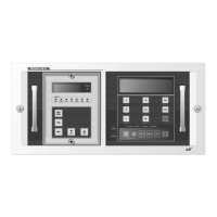
Identifies and describes the external parts and buttons of the device.
Explains the functions of each key and LED indicator on the device.
Details the functions of various keys based on the menu context.
Explains the meaning of different LED indicators and their states.
Visualizes the hierarchical structure of the device's menu system.
Lists electrical, environmental, and standard ratings for the device.
Details the measurement ranges and parameters the device can monitor.
Details operating values and time settings for OCR and OCGR relays.
Explains settings for SGR, OVR, UVR, and OVGR protection functions.
Covers the settings and definite time calculations for the POR relay.
Shows the initial display and the main menu navigation.
Details the submenus for selecting and configuring protection relays.
Outlines the submenus available under the Measurement section.
Describes the submenus for managing events and faults.
Explains the procedure for clearing event and fault logs.
Details the submenus for configuring communication parameters.
Covers submenus for configuring PT and CT ratios.
Explains the submenus for setting and viewing the device's time.
Guides on how to set the internal clock of the device.
Details submenus for accessing system diagnostic and version information.
Provides tables detailing event and fault recording capabilities.
Explains how to view measured values using the front panel.
Describes special functions accessible via key combinations.
Lists and explains various error codes generated by the device.
Details specific error types and their corresponding operational impacts or resolutions.
Lists all input and output terminals with their designations.
Shows wiring diagrams for single-phase, two-wire and three-wire configurations.
Illustrates wiring for three-phase, three-wire configurations with different CT/PT setups.
Shows wiring diagrams for three-phase, three-wire and four-wire configurations.
Illustrates wiring for zero phase current and voltage.
Depicts the operating range for the SGR protection function.
Presents the formula and graph for SI time curves.
Shows the formula and graph for Very Inverse Time (VI) curves.
Illustrates the formula and graph for Extremely Inverse Time (EI) curves.
Provides the formula and graph for Long Inverse Time (LI) curves.
Displays diagrams with dimensions for panel mounting and overall size.
Details the components for model selection (Type, Comm. Port, Protocol, Frequency).
| Model | GIPAM 115 FI |
|---|---|
| Category | Relays |
| Rated Voltage | 115VAC |
| Operate Time | 15ms max |
| Electrical Life | 100, 000 operations |
| Insulation Resistance | ≥ 100MΩ (at 500VDC) |
| Dielectric Strength | 2000V AC for 1 minute |