M10P
5
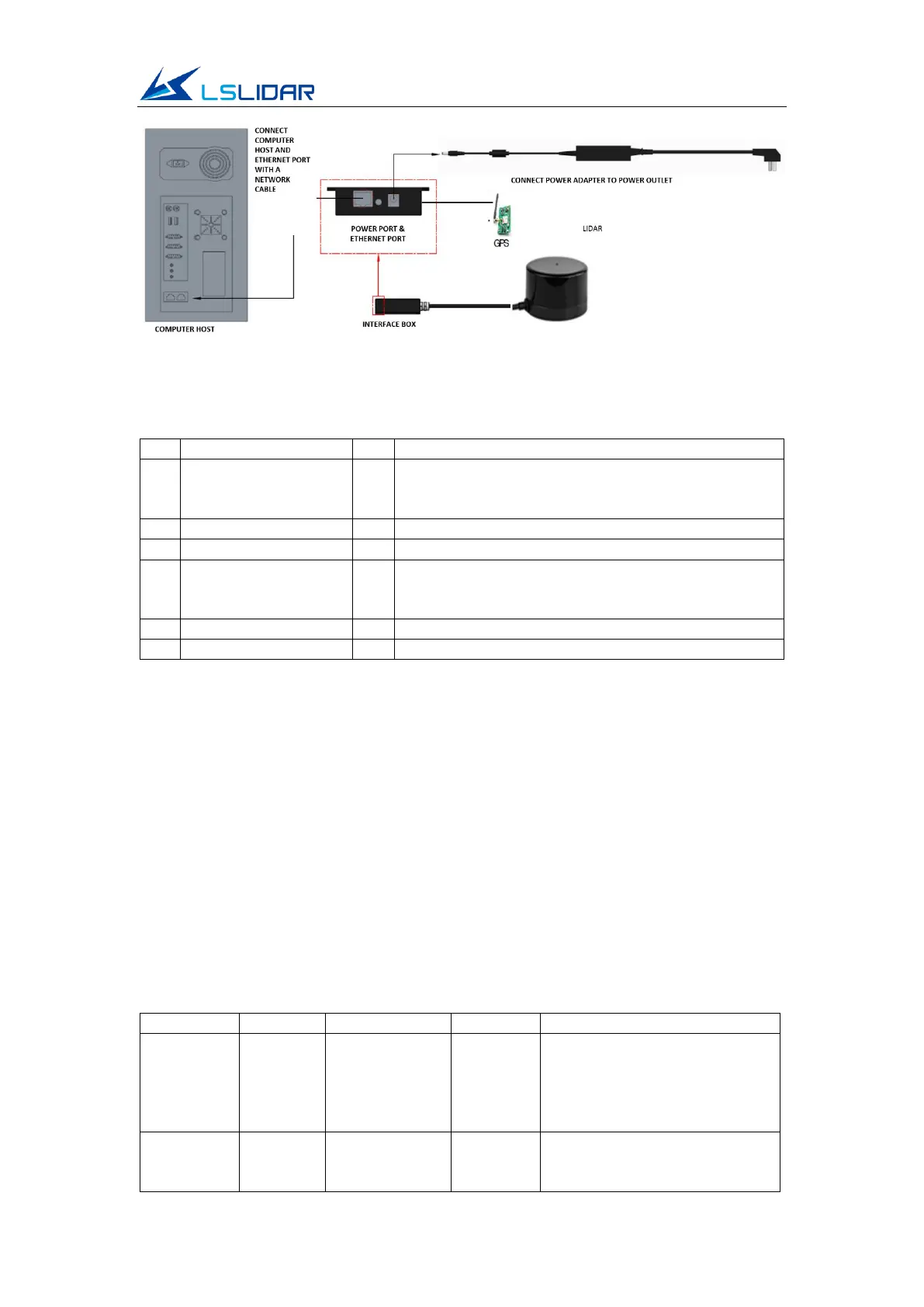
Figure 1.6 Connect All Modules Through Interface Box
Table 1.3 GPS Port Definition
TTL level range from 3.3V to 12V; its cycle is 1
second, and the recommended pulse width is more
than 5 ms
GPS
(latitude/longitude,
hour/minute/second)
RS232 level, baud rate 9600 bps
2 Electrical Parameters
The M10P lidar communicates with Fast Ethernet. An M10P lidar is made of a
high frequency ranging core, a wireless transmission system, and a rotating
subsystem. The rotating subsystem is driven by a brushless DC motor spinning
inside the system. The signal cable of M10P can be interfaced with the UART
port of the FPGA/DSP/ARM/SCM without the need for the conversion of
RS232, 422 chips. You connect an external system and the lidar and follow the
communication protocol of the lidar system to obtain the scanned point cloud
data, device information and status, and set the working mode in real-time.
Table 2.1 Electrical Parameters
The power supply not in the
range may lead to inaccurate
ranging or irreversible damage.
The output of external power
supply should be at least 5W.
Too much ripple can cause
irreversible damage to the
hardware.