Communication in Modbus mode
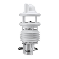
Snow depth sensor SHM 31, V2.1 53
11. Communication in Modbus mode
To make integrating the SHM 31-UMB into PLC environments easier, communication according
to the Modbus protocol is provided.
The measured values are mapped to Modbus input registers. Essentially, the same range of
measured values is available as in the UMB protocols, including the conversion to different
systems of units.
In the interests of safe device commissioning, the use of register pairs for floating point or 32-bit
integer display – which is not described in the actual Modbus standard – has been dispense
d
w
ith. All the measured values are mapped to the 16-bit registers by means of appropriate scaling.
A basic understanding of Modbus communication is assumed below. Details can be found in the
Modbus_Application_Protocol and Modbus_over_serial_line documents, for example. These
documents can be downloaded from www.modbus.org/specs.php.
11.1. Modbus connection and communication parameters
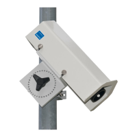
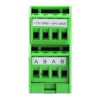
The SHM 31-UMB is connected to a Modbus logger or a Modbus network over the RS485
interface.
The SHM 31-UMB can be configured for either MODBUS RTU or MODBUS ASCII.
Basic configuration is performed with ConfigTool.NET.
Modbus operating modes: MODBUS RTU, MODBUS ASCII
Baud rate: 19200 (9600, 4800 and smaller)
Interface setting 8E1, 8N1, 8N2
Note: Modbus communication was tested with a polling rate of 1 sec. Faultless Modbus
communication of the SHM 31-UMB is not guaranteed for higher polling rates.
11.2. Addressing
The Modbus address is taken from the UMB device ID (see section 7.3).
A device with the UMB device ID 1 also has the Modbus address 1, etc.
The valid Modbus address range of 1 – 247 is smaller than the range of the UMB device IDs. If a
UMB device ID > 247 has been set, the Modbus address is set to 247.
11.3. Modbus functions
The functions of Conformance Class 0 and 1 are implemented as far as they are applicable to the
SHM 31-UMB (i.e. all the functions that work at register level).
Selected configuration settings
Selected configuration settings
Measurement values and status information
Selected configuration settings
(responds also to broadcast address)
11.
3.1. 0x03 Read Holding Registers, 0x06 Write Single Register, 0x16 Write Multiple
Registers function
The holding registers are used to make a selected set of adjustable parameters and actions also
accessible using Modbus.
Like the measured values, the parameters are mapped to 16-bit integer values, with a scaling
factor if necessary.
Registers that are allocated to parameters return the parameter’s currently active value when
read.