5
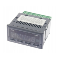
N31U User manual
Comments concerning safety
• Assembly and installation of the electrical connections should conducted
only by a person authorised and certicated to perform assembly of elec-
tric devices.
• Always check the connections before turning the meter on.
• The meter is designed to installation and usage in the industrial electro-
magnetic environment.
• A switch or a circuit-breaker should be installed in the building or facility. It
should be located near the device, easily accessible by the operator, and
suitably marked.
• Removal of the meter electronics during the warranty period voids
the warranty.
4 INSTALLATION
4.1 Installation method
The N31U meters are designed to be mounted in a panel. Prior to installation a
92+0.6 x 45+0.6 mm slot must be made in the panel. The maximum thickness
of the panel material cannot exceed 6 mm. The meter should be mounted from
the front of the panel with disconnected meter connection strips.
Before inserting the meter into the panel check the correct position of the
meter seal and make sure that the edges of the panel are not sharp what co-
uld damage the seal. After inserting the meter into the slot, mount it with the
mounting brackets provided in the meter set (Fig. 2).
Fig. 2: Meter xing.

 Loading...