6
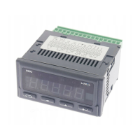
N31U User manual
Electrical connections of the meter should be made with the wires with the
cross-section up to 2.5 mm2. Detachable sockets with the plugs of 5.08 mm
pitch can be used for the connections.
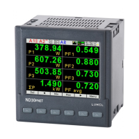
The external dimensions of the meter are shown in Fig. 3
4.2 External connection diagram
The meter’s electrical connections must be made with wires whose cross-
-section does not exceed 1.5 mm2 for terminals numbered 1 to 10 (lead-in
grid of 3.81 mm) and 2.5 mm2 for terminals numbered 11 to 18 (lead-in grid of
5.08 mm).
The view of the meter from the connectors’ side is shown in Fig. 5. The upper
terminal strip is optional and depends on the accessories of the meter.
The circuits of successive groups of the terminals are separated from each
other, as shown in Fig. 4.
Fig. 3: Meter overall dimensions.

 Loading...