7
N31U User manual
Note: Unused terminals of the terminal strips must not be connected to
any signals.
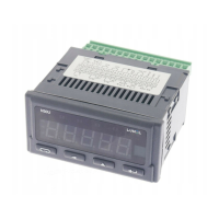
Detailed description of the signals is shown in the table below, and the con-
nection of the measuring signals is shown in Fig. 6.
Fig. 4: Galvanic isolation of the N31U meter.
Fig. 5: Signals on the terminal strips.
Supply
Alarm
Measuring inputs, output 10/24 V d.c.

 Loading...