8
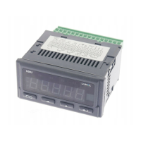
N31U User manual
The connection of the basic measured signals is shown below. The inputs not
used in the conguration should be left unconnected.
Terminal Function Description
1, 2, 3, 4, 5,
7, 8
Measuring inputs Measuring inputs for connecting sensors, transducers or output signals from
the other devices. Examples of the connections are shown in Fig. 6.
6, 9 Supply output Auxiliary supplying output (24 V) for supplying the potentiometers, trans-
ducers, e.g. head-mount transducers supplied by a current loop. Maximum
current carrying capacity of the output is 30 mA.
11, 12, 13 RS-485 RS-485 interface signals
14, 15 Alarm Alarm output, which is NO relay contact.
16, 17, 18 Power supply Meter power supply connection. Depending on the power supply voltage
range, use connectors 17-18 or 16-17.
Note: Connecting the power supply to connectors
16-18 will damage the meter!
Standard signals 0...10 V
(range -11…11 V)
Standard signals 0/4...20 mA
(range -24...24 mA).
Thermocouples, thermoelectric sensors
(thermocouple)
Standard shunts: 60 mV,
150 mV, 300 mV
(measuring range respectively: -75...75
mV, -155...155 mV,
-310...310 mV).
Thermoresistive sensors or resistor in a
three-wire system
Thermoresistive sensors or resistor in a
two-wire system

 Loading...