28
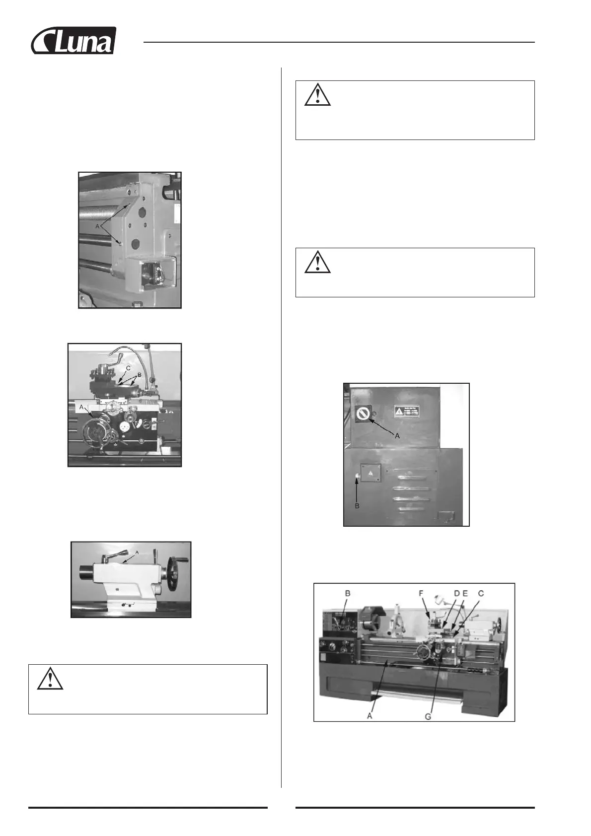
Fig. 9
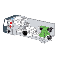
Fig. 6
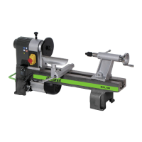
Fig. 7
CAUTION
Follow coolant manufacturer’s recommendations for use,
care, and disposal.
WARNING
All electrical connections must be completed by a qualified
electrician! Failure to comply may cause serious injury
and/or damage to the machinery and property!
WARNING
Disconnect the machine from power source! Failure to do
so may cause serious injury!
Kuva 10
3. Apron - Oil must be between indicator marks in the oil sight glass (A,
Fig. 5). Top off with Mobil DTE® Oil Heavy Medium. Remove oil
plug (B, Fig. 5) on upper right of apron to fill. To drain, remove drain
plug on bottom of apron. Drain oil completely and refill after the first
three months of operation. Then, change oil in the apron annually.
Pull knob (C, Fig. 5) on the one-shot lube system and hold for several
seconds to allow oil to fill the pump. When the knob is released, oil
will flow through various oil lines to lubricate the ways and cross slide
surface. Perform this twice daily or as needed. When the oil level is
below the indicator mark, oil must be added.
4. Leadscrew & Feed Rod: Lubricate two ball oilers on the right side
bracket (A, Fig. 6) with Mobil DTE® Oil Heavy Medium oil daily.
5. Saddle: Lubricate ball oiler (A, Fig. 7) on handwheel shaft with Mobil
DTE® Oil Heavy Medium oil daily.
6. Compound Rest: Lubricate four ball oilers (B, Fig. 7) on top of com-
pound slide with Mobil DTE® Oil Heavy Medium oil daily.
7. Cross Slide: Lubricate one ball oiler (C, Fig. 7) with Mobil DTE® Oil
Heavy Medium oil daily.
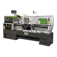
Fig. 8
8. Tailstock: Lubricate one ball oiler (A, Fig. 8) on top of tailstock with
Mobil DTE® Oil Heavy Medium oil daily.
Coolant Preparation
1. Remove access cover on tailstock end at the rear base of the lathe.
Make sure coolant pump has not shifted during transport.
2. Pour four gallons (approx.) of coolant mix into the chip pan.
3. After machine has been connected to power, turn on coolant pump and
check to see that the coolant is cycling properly.
4. Replace access cover.
Electrical Connections
The main motor is rated at 7-1/2 HP (5.5KW), 230/460V and comes from
the factory prewired at 230V. Confirm power available at the lathe's loca-
tion is the same rating as the lathe. Power is connected properly when pul-
ling up on the forward-reverse lever causes the spindle to rotate counter-
clockwise as viewed from the tailstock. If the chuck rotates in the clock-
wise direction, disconnect the lathe from the power source, switch any
two of power leads (except ground wire green), and connect the lathe to
the power source.
To switch from 230V to 460V operation
Main Motor: Change the wires according to the diagram on the outside
of the motor junction box.
Transformer: Open electrical panel on rear of machine on the headstock
side. Switch wire from 230V terminal to 460V terminal as outlined on the
transformer.
Coolant Pump: Open access panel on the base at the tailstock end.
Change wires in coolant pump junction box according to diagram on the
outside of the junction box over.
Main Power Switch: (A, Fig.9) Turns power to machine on and off.
Power Source Cable Receiver: (B, Fig.9) Make sure the lathe is properly
grounded.
General Description
Lathe Bed. The lathe bed (A, Fig. 10) is made of cast iron with low vibra-
tion and high rigidity. Two precision ground v-slideways, reinforced by
induction hardening and grinding, are an accurate guide for the carriage
and headstock. The main drive motor is mounted in the stand below
headstock.
 Loading...