30
10. Half Nut Lever: (D, Fig. 13) Located in the front of the apron assem-
bly. Used for threading.
11. Feed Engage Lever: (G, Fig.13) Located in the front of the apron as-
sembly. Pull lever up to engage. Push lever down to disengage.
12. Adjustable Feed Clutch: (F, Fig.13) When the machine is overloa-
ded, it can slip. Then cutting rate must be reduced. Note: This setting
has been calibrated at the factory and should not need adjustment. If
adjustment is necessary, follow the diagram on the front of the apron.
13. Cross Traverse Hand Wheel: (H, Fig.13) Located above the apron
assembly. Clockwise rotation moves the cross slide toward the rear of
machine.
14. Compound Rest Traverse Handle: (J, Fig.13) Located on the end of
the compound slide. Rotate clockwise or counter-clockwise to move,
or position.
15. Tool Post Clamping Lever: (K, Fig.13) Located on top of the tool
post. Rotate counter-clockwise to loosen and clockwise to tighten.
Fig. 17
Fig. 16
Fig. 14
Fig. 15
Fig. 18
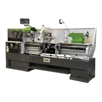
16. Tailstock Quill Clamping Lever: (A, Fig.14) Located on the
tailstock. Rotate clockwise to lock the sleeve. Rotate counter-clockwi-
se to unlock.
17. Tailstock Clamping Lever: (B, Fig.14) Located on the tailstock.
Lift up to lock. Push down to unlock. If the tailstock has a heavy load,
tighten the hexagon head at right side of the tailstock for auxiliary
locking.
18. Tailstock Quill Traverse Hand Wheel: (C, Fig.14) Rotate clockwise
to advance the quill and counter-clockwise to retract it.
19. Tailstock Off-Set Adjustment: (D, Fig.14) Two hex socket cap scre-
ws located on the tailstock base are used to off-set the tailstock for
cutting tapers. Loosening one screw while tightening the other will
off-set the tailstock. Do not clamp the tailstock lock handle when ad-
justing.
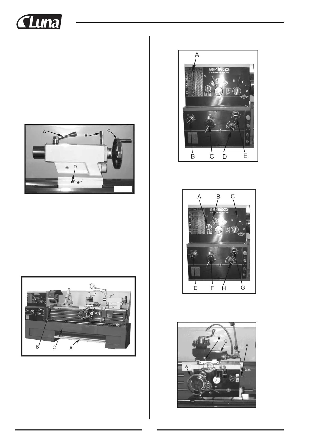
20. Foot Brake: (A, Fig.15) The connecting rod mechanism is in the bed
stand. The braking device is in the pulley of the headstock. Depress
the pedal to stop all lathe functions. (Caution: lathe still has power.)
21. Micro Carriage Stop: (B, Fig. 15) can be used during manual feed
operation. The dial can be turned for fine tuning the position of the
stop. The micro carriage stop can be moved along the bed by loose-
ning the two socket head cap screws found on the bottom side of the
stop.
22. Bed Cover: (C, Fig. 15) can easily be removed to clean out the stand.
Operation
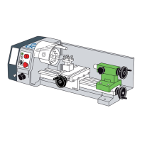
Feed and Thread Selection
1. Reference the feed and thread chart. Found on front of the headstock
(A, Fig.16).
2. Move levers and knobs (B, C, D, E, Fig.16) to the appropriate posi-
tion according to the feed and thread chart.
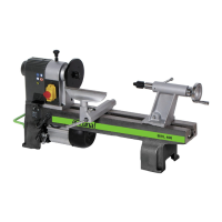
Thread Cutting
1. Set forward/reverse lever (A, Fig.17) to desired direction.
2. Set selector levers (B, C, Fig.17) to desired R.P.M.
3. Select desired thread using levers (E, F, H, G, Fig.17).
 Loading...