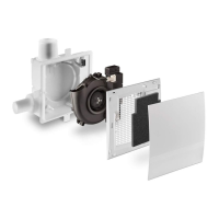
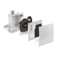
Assembly – Electrical Installation and Electrical Connection
Caution! All assembly work on the fan must only be carried out when power has been disconnected from all
terminals!
Make sure all connection lines are de-energized before connecting the fan to the power supply !
(disconnection from power supply with at least 3 mm contact opening, e.g. all-pole circuit-breaker)
Each circuit connected to the ventilation system must be fitted with residual current protection (e.g. a RCD
switch)! Electrical connections must be carried out by qualified staff only!
Additional installations and electrical components in this ventilation system are not admissible!!
Triggering can be made via the
universal control 5/UNI and the
added feature control TAC. Re-
spective installation instructions
apply accordingly.
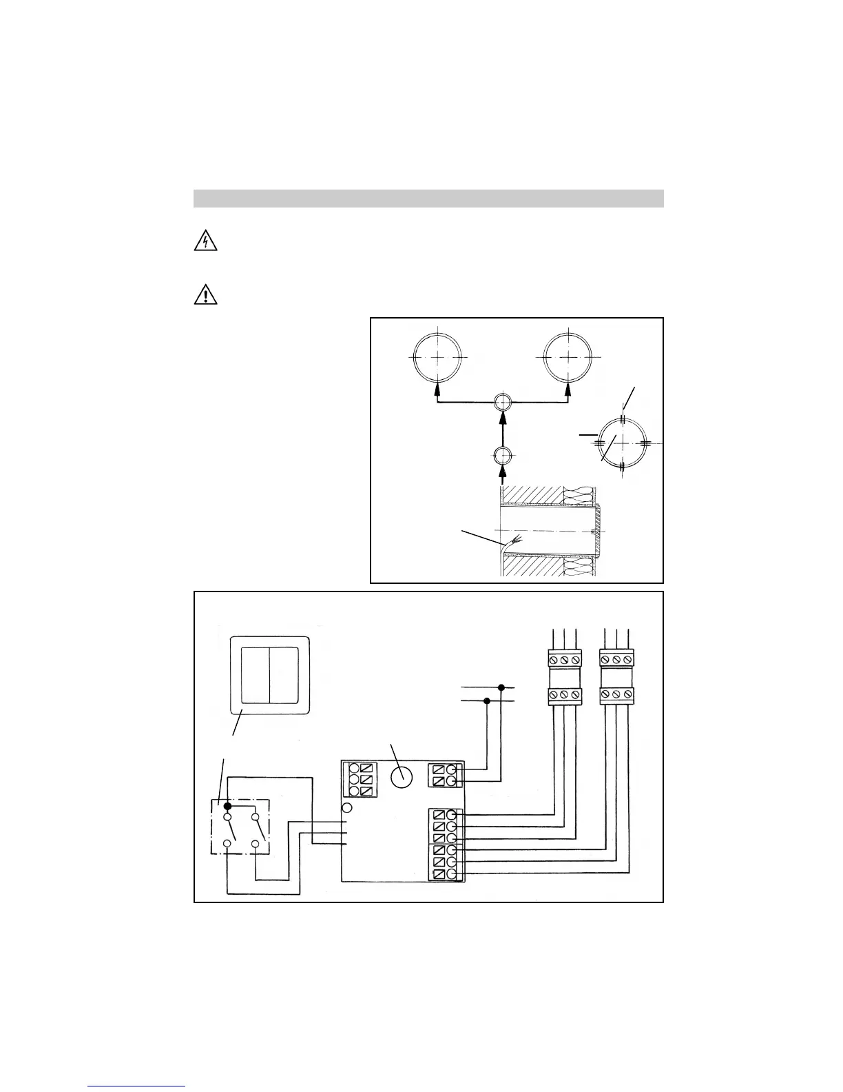
Select the position of the switch.
Slit the cable ducts (power cable +
cable to device pairs) and the
tubes (2 cm deep). Install the pow-
er cable (e.g. 3 x 1.5 mm² ) and
the cables to the device pairs (e.g.
3 x 0.75 mm² ). Prepare the cables
to the device pairs in the tube.
Circuit and switches are connected
in accordance with the wiring dia-
gram below.
5
➃
Power
Switch
Device 1
Out/In
Device 2
In/Out
horizontal
vertical
also slit tubes
for cables
only slit
tubes in
these four
sections
Joint box
Safety Instructions
Device cable pre-
pared in tube
I III II
0
Important! Set the
coding switches to
the functions re-
quired for e² mini
(refer to Installation
Instructions E 148).
Deviating coding
switch settings are
inadmissible and
result in malfunc-
tions!
Series switch 5/W2U
Front view
Universal
control
5/UNI
grey
red
black
W1 W2
+ 12V
-
rt bl li rt bl li
Device (e)1 Device (e)2
Out/In In/Out
5