2-6
CDA3000 Operation Manual
2 Mechanical installation
.
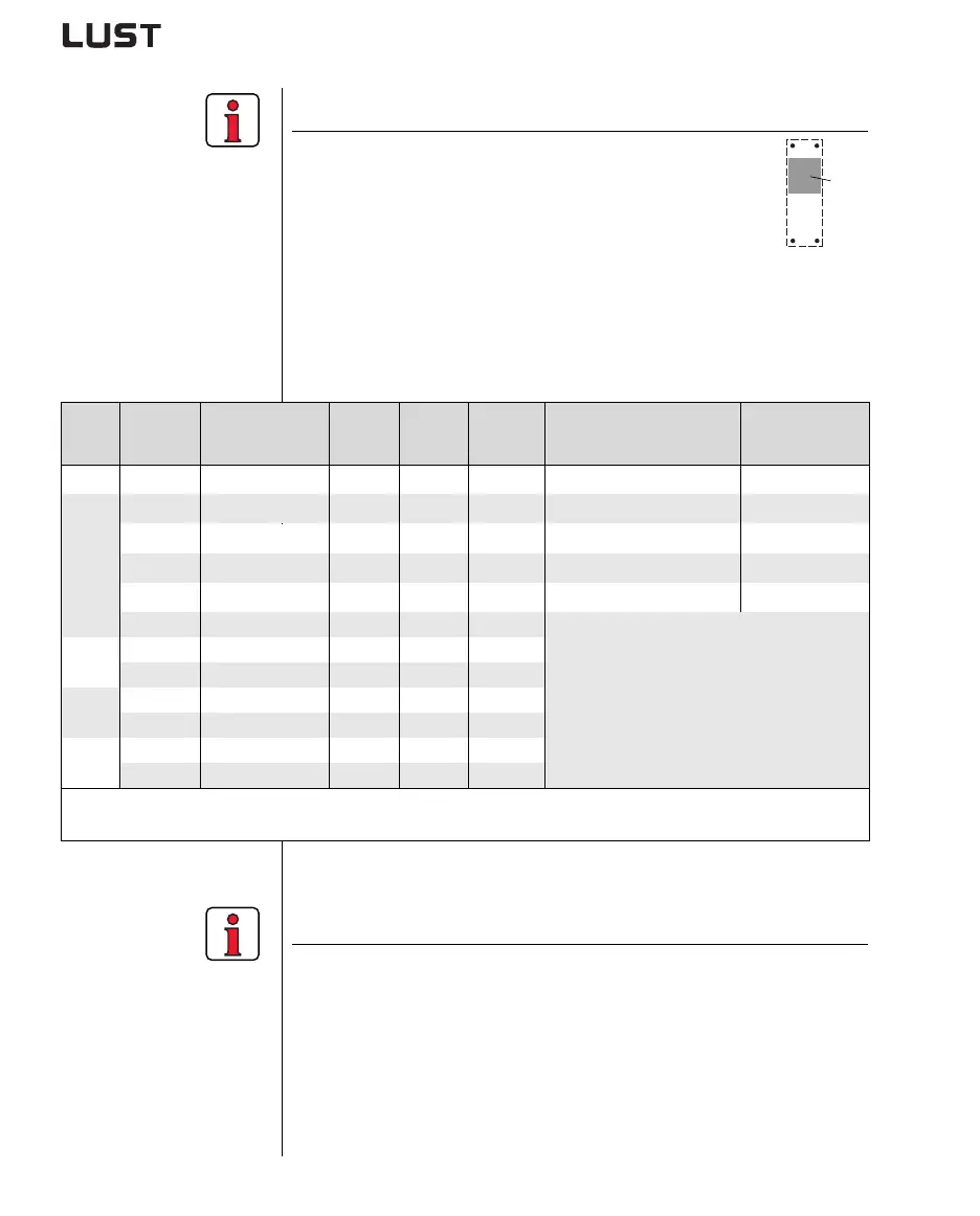
Note the following points:
• Cooling can be attained either by a sufficiently large
backing plate (see Table 2.4) or by an additional cooler.
The cooler must be mounted centrally behind the
hottest area (1) of the device.
• The temperature on the rear panel of the inverter
module must not exceed 85.0 °C. At a temperature
> 85° C the device shuts down automatically. It can only be
restarted when it has cooled.
• Required evenness of contact surface = 0.05 mm, maximum
roughness of contact surface = roughness factor 6.3
(1)
Size Power Inverter module
P
V
at
4 kHz
P
V
at
8/16 kHz
R
thK
3)
[K/W]
Backing plate (unvarnished
steel min. cooling surface
Ambient
temperature
BG1 0.75 kW CDA32.004,Cx.x 48 W 55 W 0.05 650x100mm = 0.065m²
45°C
1)
, 40°C
2)
BG2
1.1 kW CDA32.006,Cx.x 75 W 82 W 0.05 650x460mm = 0.3m²
45°C
1)
, 40°C
2)
1.5 kW CDA32.008,Cx.x 95 W 105 W 0.05 650x460mm = 0.3m²
45°C
1)
, 40°C
2)
0.75 kW CDA34.003,Cx.x 55 W 70 W 0.05 None
45°C
1)
, 40°C
2)
1.5 kW CDA34.005,Cx.x 80 W 112 W 0.05 650x460mm = 0.3m²
45°C
1)
, 40°C
2)
2.2 kW CDA34.006,Cx.x 106 W 148 W 0.05
An additional cooler is required to supply
adequate cooling.
Project planning notessee appendix A.4
If you have any further questions please
consult your project engineer.
BG3
3.0 kW CDA34.008,Cx.x 135 W 162 W 0.03
4.0 kW CDA34.010,Cx.x 172 W 207 W 0.03
BG4
5.5 kW CDA34.014,Cx.x 210 W 268 W 0.02
7.5 kW CDA34.017,Cx.x 255 W 325 W 0.02
BG5
11 kW CDA34.024,Cx.x 315 W 400 W 0.015
15 kW CDA34.032,Cx.x 400 W 510 W 0.015
1) At a power stage clock frequency of 4 kHz 2) At a power stage clock frequency of 8 kHz
3) Thermal resistance between active cooling surface and cooler
Table 2.4 Required cooling with cold plate
Note the following points:
• The backing plate must be grounded over a large area.
• For mounting in switch cabinets with convection (= heat loss is
discharged to the outside via the cabinet walls) an internal air
circulation fan must always be fitted.
• The best result for effective EMC installation is attained with a
chromated or galvanized backing plate. If backing plates are
varnished, the coating must be removed in the area of the contact
surface!
 Loading...
