4)Zero adjustment :
Due to the consideration of the existing " stray
capacitance " of the internal circuit board or the test
alligators. For the 40 nF & 400 nF range, it should to
make the zero adjustment procedures before make the
measurement first. Open the input terminal & not
connecting the measured capacitor, push the " REL.
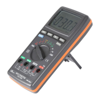
Button " ( 3-4, Fig. 1 ), the display will show zero value.
Then connect the measuring capacitor again & make the
measurement following.
5)For the capacitance measurement, the meter is always
under the " auto range " mode., it will select the suitable
measurement range automatically.
5-8 Frequency, Duty Measurement
Frequenc
1)Connect BLACK test lead into " COM " terminal ( 3-11,
Fig. 1 ).
2)Connect RED test lead into " V " terminal ( 3-12, Fig. 1 ).
3)Select the " Function rotary switch " ( 3-8, Fig. 1 ) to the
" Hz " position then push the " Hz/DUTY Button " ( 3-3,
Fig. 1 ) for display show " Hz " .
4)For the FREQUENCY measurement, the meter is always
under the " auto range " mode, it will select the suitable
measurement range automatically.
DUT
ll the measuring procedures are same as above
Frequency measurement except push the " Hz/DUTY "
( 3-3, Fig. 1 ) for display show " % ".
15