2 | Lutron
EcoSystem to 0 – 10 V- Interface | Install Guide
www.lutron.com/ecosystem
Step 1: Mount Interface
0 –10 V- interfaces must be mounted to or within a
grounded, metal ULR/NECR recognized electrical enclosure,
either a lighting fixture or a suitable UL508 listed enclosure.
To mount to a junction box, use Lutron part 2441317. Follow
applicable local and national codes.
Interface must be mounted within 10 ft (3 m) of the driver it is
controlling.
WARNING - Electric Shock Hazard. May Result
in Serious Injury or Death. To avoid the risk of
electric shock, do not install while energized. Do not
connect any electrically live circuits to the interface
prior to installation.
1. Use the threaded mounting studs on the interface for
mounting.
2. Use the dimensioning guide below to properly mount the
interface.
3. Use provided star washer between interface and enclosure.
4. Tighten provided nuts on mounting studs.
Step 2: Wire Interface to Driver(s)
WARNING - Electric Shock Hazard. May
Result in Serious Injury or Death. To avoid the
risk of electric shock, do not wire live. Interrupt
power via breaker before wiring between the
interface and a driver.
Two low-voltage and two line-voltage wires are used
between the interface and drivers. The terminals are
color coded as follows:
ORANGE = Switched Hot (120 – 277 V~) (SL)
WHITE = Neutral (N)
GRAY = - 0 – 10 V-
PURPLE = + 0 – 10 V-
Use the following steps to wire an interface to a driver.
Step 2a: Line Voltage Wiring
Drivers must be selected for appropriate input voltage.
Verify that a 120 V~ driver is used only with 120 V~
mains, and a 277 V~ driver is used only with
277 V~ mains. Interfaces may be used at either
voltage. All drivers connected to the same interface
must be rated for the same input voltage. Interfaces
can only support up to 2 A of attached driver load
current, with a maximum of 5 drivers.
1. Use 16 AWG to 18 AWG (1.5 mm² to 0.75 mm²) solid
conductors to wire between the interface and driver.
2. Wire the interface’s Switched Hot (SL) (ORANGE)
output to the driver’s Line / Hot input.
3. Wire the interface’s Neutral (N) (WHITE) to the driver’s
Neutral input.
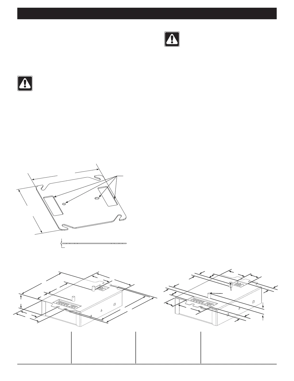
A 4.20 in (107 mm)
B 1.00 in (25 mm)
C 3.00 in (76 mm)
D 4.90 in (124 mm)
E 4.60 in (117 mm)
(mounting center)
F 1.42 in (36 mm)
G 1.99 in (51 mm)
H 1.11 in (28 mm)
I 2.00 in (51 mm)
J 1.60 in (41 mm)
K 0.33 in (8.3 mm)
L 0.65 in (16.5 mm)
M 0.75 in (19 mm)
N 1.73 in (44 mm)
O 1.33 in (34 mm)
P 0.74 in (19 mm)
Q 0.32 in (8 mm)
R 0.29 in (7 mm)
Mounting Dimensions
Junction Box Mounting Plate Dimensions
B
F
G
J
C
H
A
E
D
I
Connector Location Dimensions
M
N
O
P
R
K
Q
L
K
Q
L
8-32 Threaded
Studs
4.070 in
(103 mm)
4.070 in
(103 mm)
0.063 in
(1.6 mm)
Features
designed to
interface with
the TVI-LMF-2A
module.
Features designed to interface with a 4 in (102 mm) square metal junction box.
 Loading...