Lutron | 3
EcoSystem to 0 – 10 V- Interface | Install Guide
Customer Assistance: +1.844.LUTRON1
Step 2b: 0 – 10 V- Wiring
WARNING - Risk of Fire or Electric Shock.
May Result in Serious Injury or Death. Do not
interconnect the outputs of different Class 2
circuits. Do not tie 0 – 10 V- output of device to
EcoSystem link or another Class 2 source.
Wire per Class 2 wiring regulations. If EcoSystem link
is wired per Class 1, the EcoSystem wires need to be
separated from the 0 – 10 V- wires by a barrier or 0.25 in
(6mm) minimum.
1. Use 16 AWG to 18 AWG (1.5 mm² to 0.75 mm²) solid
conductors to wire between the interface and driver.
2. Wire the interface’s 0 – 10 V- + terminal (PURPLE) to the
driver’s 0 – 10 V- + wire (typically purple).
3. Wire the interface’s 0 – 10 V- – terminal (GRAY) to the
driver’s 0 – 10 V- – wire (typically gray).
Step 3: Wire Mains to the Interface
Line / Hot and Neutral from a distribution panel are required
for the interface. Verify that the mains voltage matches the
voltage rating of the driver that the interface is controlling.
Use the following guidelines for wiring mains voltage to the
interface.
WARNING - Electric Shock Hazard. May Result in
Serious Injury or Death.To avoid the risk of electric
shock, do not wire live. Interrupt power via breaker
before wiring between the interface and a driver.
1. Interface terminals only accept solid wire. Join mains input Hot
and Neutral to 16 AWG to 18 AWG (1.5 mm² to 0.75 mm²)
solid wire before connecting to an interface.
+
–
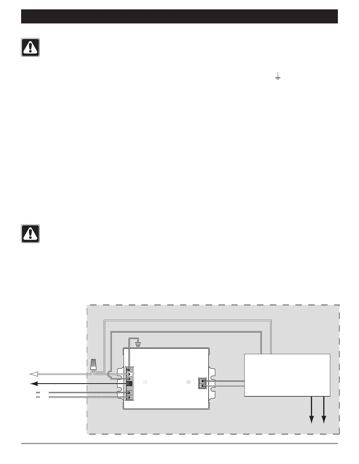
Wiring Diagram
Wiring between an interface and a driver
EcoSystem to
0 – 10 V- Interface
To LEDs
0 – 10 V- LED Driver
(by others)
Neutral
Line / Hot
Ground
Switched Hot
Line In
Neutral
EcoSystem
Link (E1, E2)
0 – 10 V-
Wiring within fixture
E2
E1
To breaker panel (unswitched)
Step 3: Wire Mains to the Interface (continued)
2. Wire the Line / Hot input to the HOT (L) (BLACK) terminal on
the interface.
3. Wire the Neutral input to the NEUTRAL (N) (WHITE) terminal
on the interface. A pigtail wire is necessary.
4. Wire ground wire to the GROUND (
) (GREEN) terminal on
the interface.
5. Make sure the driver(s) are correctly wired to the interface
(step 2).
Step 4: Wire EcoSystem Link
An EcoSystem link supply controls up to 64 ballasts and
interfaces. EcoSystem link wiring may be run daisy-chain,
t-tap, and/or star pattern. Link wiring may be either
Class 1 or Class 2.
Class 1: Low voltage link wiring may be run with mains
voltage to any fixture the link is controlling.
Class 2: Low voltage link wiring must be separated from
all mains and Class 1 wiring by a barrier or at least 0.25 in
(6mm). Consult all applicable national and local codes for
compliance.
Lutron recommends using two different colors for E1 and
E2 (EcoSystem link) wire. This helps prevent link wiring
mistakes.
Use the following guidelines for wiring the EcoSystem link
to the interface.
White
White
Black
Purple
Purple
Ground
0 – 10 V -
Output
Green
Neutral
Switched Hot/Out
Constant Hot/In
EcoSystem
Digital Link
(bottom view)
Gray
Purple/White
Orange
 Loading...