369374a 5 08.07.12
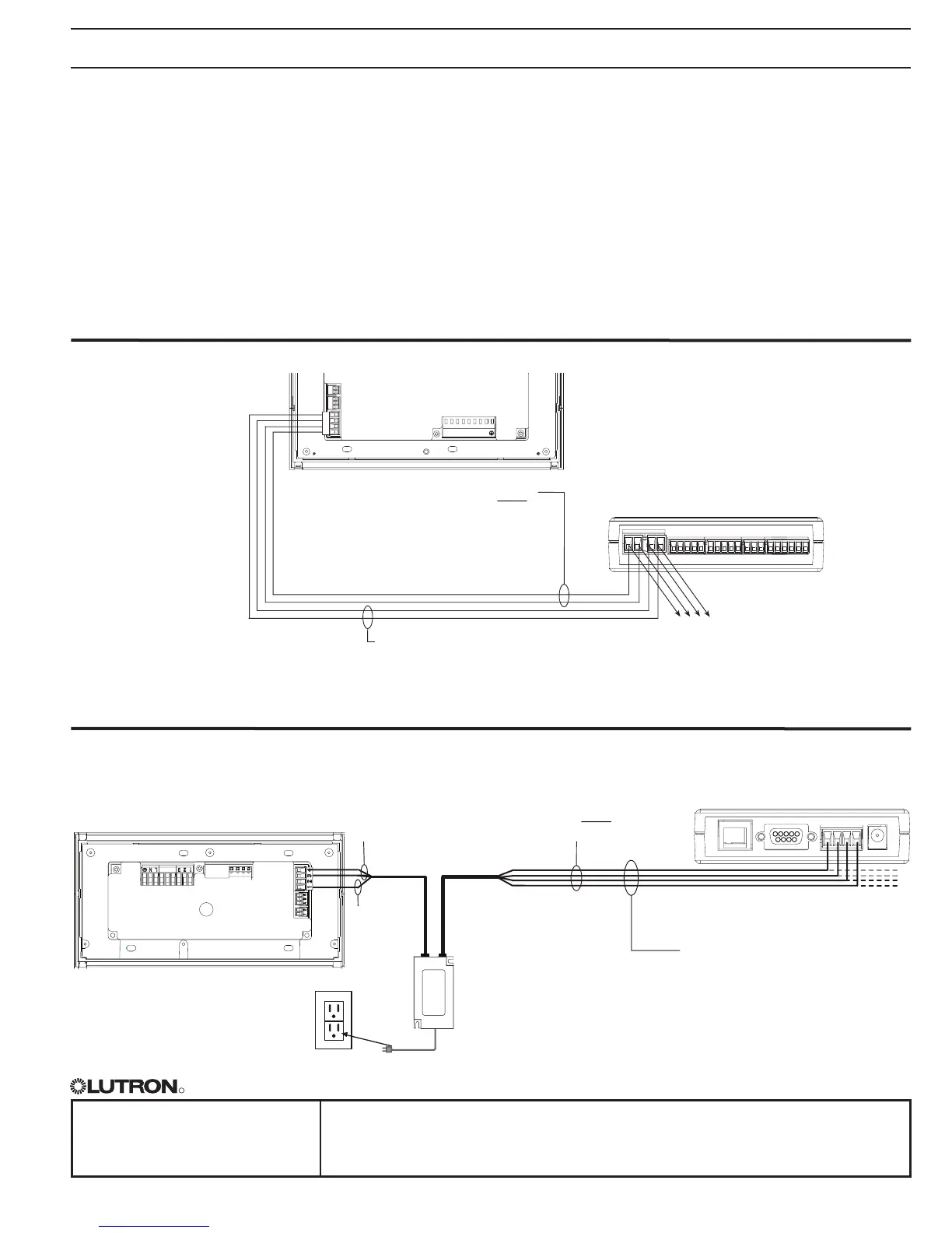
QS Link Wiring Methods (choose one)
Powered by GRAFIK Eye® QS Control Unit
Powered by a QS Link Power Supply
1234
12
ABC
123456LN
To additional wallstations/
control interfaces
To additional wallstations/
control interfaces
RearViewof
GRAFIKEye
® QS
ControlUnit
RearViewof
GRAFIKEye
® QS
ControlUnit
QS
Link
QS
Link
QSLink
1:Common
2:Power
3:MUX
4:MUX
DataLink:
4:MUX
3:MUX
SeeQSLink
WireSizestable
previous page
IECPELV/NECClass2Powerwiring:
2:Power
1:Common
SeeQSLinkWireSizes
table previous page
•SystemcommunicationusesIECPELV/NEC®Class2
wiring.
•Followalllocalandnationalelectricalcodeswhen
installingIECPELV/NEC
®Class2wiringwithline
voltage/mains wiring.
•Eachterminalacceptsuptotwo18AWG(1.0mm²)
wires.
•Totallengthofcontrollinkmustnotexceed2000ft
(610m).
•TypicalWireSizes:SeeQSLinkWireSizestable,
previous page.
•Connecttheterminal1,3,and4connectionstoall
control units, wallstations, and control interfaces in
theQSsystem.Forterminal2connectivity,please
refer to the wiring diagrams below.
•TheQSE-IOcontrolinterfacecanbepoweredbythe
followingdevices:
-GRAFIKEye
® QS control unit
-QSlinkpowersupply(QSPSmodelnumbers)
- Quantum
®LightManagementHub
(see Quantum
® system documentation)
-EnergiSavrNode
TM QS
4321
LutronCable
SeeQSLinkWireSizestable
previous page
QSPS-P1-1-50
(providesupto8
power draw units)
To power source
(1)18AWG
(1.0mm
2
)
Common
(1)twistedpair
22AWG
(0.5mm
2
)