11
en
0698-401 MD1xL / MD2xL - 08/2020
• Install the maintenance unit with an air connection of at least G 1/4 in the immediate vicinity of the
compressedairmotor(1).Usearesin-freeandacid-freemineraloilwithaviscosityof20to30mm²/s
intheoiler(3).Theoilconsumptionshouldbe1dropperminuteasaminimum.
• Theairlter(3)requiresregularmaintenanceduringwhichthetrappedcondensationwaterisdrained
andthelteriscleaned.
• Thecompressedairmotorwillachievemaximumperformanceat6bar(87psi).Thepressureinthe
pneumaticsystemexceeding6bar,apressureregulator(3)mustbeinstalled.Adjustmentofthepressure
regulator(3)mustbeeectedwiththemotorrunning.
• Installanairhose(2)of13mminsidediameterbetweenmaintenanceunitandcompressedairmotor
tominimizethepressurelosses.
• Use a stop valve in the pressure line in order to connect and disconnect the motor without pressure.
• Note the resulting pressure loss when using quick-action couplings.
Recommendation for compressed air supply
• TheclassicationofthecompressedairqualitycanbetakenfromISO8573-1:2010.
• Standard values of compressed air quality are e.g. to be found in VDMA 15390-1: 2014-12.
• For lubricated air, a minimum compressed air quality by ISO 8573-1: 2010 [-: 4: 4] is recommended.
• For non lubricated air, a minimum compressed air quality by ISO 8573-1: 2010 [6 3: 3] is recommended.
• Excessivewatercontentinthecompressedaircancausefreezingofthewaterparticles.Thismaybethe
causefordamagingthevanesorcloggingthemuer,whichmayaecttheperformanceofthemotor.
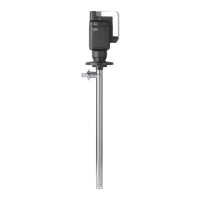
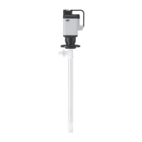
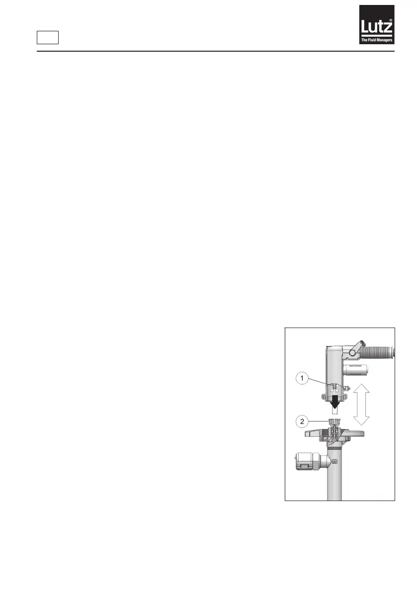
4.2 Assembly of pump tube to the motor
3Motorisswitchedo
► Connect the motor with the pump tube.
► Turn the motor slightly to ensure that the driver (→Fig.2,Item1)
engages in the coupling (→Fig.2,Item2).
► Firmly connect the motor and pump tube by means of the
handwheel(right-handthread)(→Fig.2).
Fig. 2
 Loading...