Do you have a question about the Luxman M-03 and is the answer not in the manual?
Details power output, input sensitivity, impedance, frequency response, S/N ratio, THD, and dimensions.
Details specifications for the BTL mode, including THD and maximum power output.
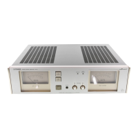
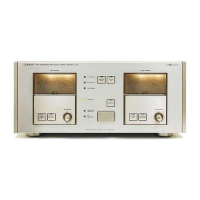
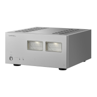
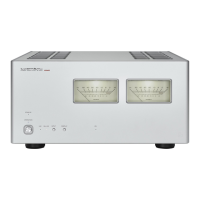
Identifies controls and indicators on the front panel of the audio unit.
Identifies connections and switches on the rear panel of the audio unit.
Provides step-by-step instructions for removing the heatsink and main amplifier boards.
Outlines necessary connections and initial control settings for performing adjustments.
Details the procedure for adjusting the idling current of the amplifier.
Describes the process for calibrating the power level indicators.
Illustrates adjustment points on the left main amplifier circuit board for the UQ model.
Illustrates adjustment points on the right main amplifier circuit board for the UQ model.
Illustrates adjustment points on the display circuit board for the UQ model.
Illustrates adjustment points on the left main amplifier circuit board for the AD model.
Illustrates adjustment points on the right main amplifier circuit board for the AD model.
Illustrates adjustment points on the display circuit board for the AD model.
Illustrates the signal path through the amplifier channels and internal circuits.
Depicts the power distribution and control signal paths within the unit.
Shows component placement and wiring for the left and right main amplifier boards.
Details component placement and wiring for the input and attenuator volume boards.
Shows component placement and wiring for the speaker terminal circuit board.
Lists wire colors and their corresponding meanings for internal connections.
Shows component placement and wiring for the display and turbo amplifier boards.
Details component placement and wiring for speaker switch, display switch, and LED O/B boards.
Shows component placement and wiring for the power supply and prime fuse circuit boards.
Lists transistors, diodes, capacitors, and resistors for the left main amplifier board.
Lists transistors, diodes, capacitors, and resistors for the right main amplifier board.
Lists components for the power supply circuit board.
Lists components for the speaker terminal circuit board.
Lists components for the input circuit board.
Lists ICs, transistors, diodes, capacitors, and crystal for the display circuit board.
Lists components for the turbo amplifier circuit board.
Lists components for the LED O/B board, LEDs, fuses, and other miscellaneous parts.
Illustrates the method for packing the unit for shipment.
Lists parts for the front panel, top/rear covers, and various knobs.
Lists various screws, washers, insulators, and fasteners used in cabinet assembly.
Lists shafts, brackets, fuse holders, and associated labels for the cabinet.
Shows an exploded view of the front, top, and rear sections of the unit's cabinet.
Illustrates the exploded view of the main chassis and major internal components.
Highlights the placement of wiring harnesses and smaller assembly parts.
Shows pinout diagrams and functions for various integrated circuits.
Illustrates pinout diagrams and functions for the M5238P integrated circuits.
Shows pinout diagrams for common 2SA and 2SC series transistors.
Continues showing pinout diagrams for various 2SA and 2SC series transistors.
Illustrates pinout diagrams for FETs and DTA/DTC series transistors.